Capillary core structure and preparation method thereof

A capillary core and microporous structure technology, applied in lighting and heating equipment, indirect heat exchangers, etc., can solve the problems of few vaporization core sites, low heat transfer power of heat pipes, poor capillary performance, etc., and achieve a simple and efficient preparation method. , Enhance the effect of nucleate boiling and good shock resistance

Pending Publication Date: 2019-03-01
SOUTH CHINA UNIV OF TECH +1
View PDF7 Cites 1 Cited by
  • Summary
  • Abstract
  • Description
  • Claims
  • Application Information

AI Technical Summary

Problems solved by technology

However, compared with other capillary wick structures, the traditional grooved capillary wick structure usually has disadvantages such as poor capillary performance and fewer vaporization core sites due to its smooth surface, which leads to the evaporation section being easily evaporated to dryness under high heat flux. The coefficient is low, the overall thermal resistance is large, and the heat transfer power of the heat pipe is low, etc.

Method used


Image

  • Capillary core structure and preparation method thereof
  • Capillary core structure and preparation method thereof
  • Capillary core structure and preparation method thereof

Examples


Embodiment 1

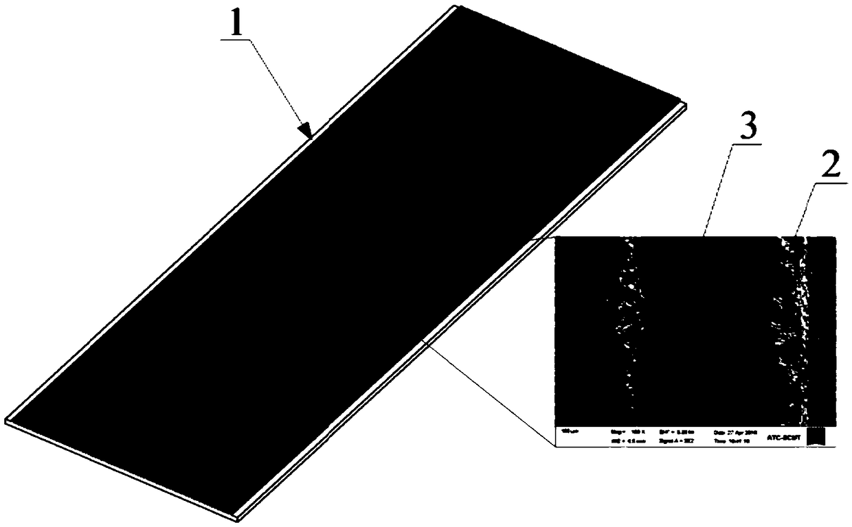
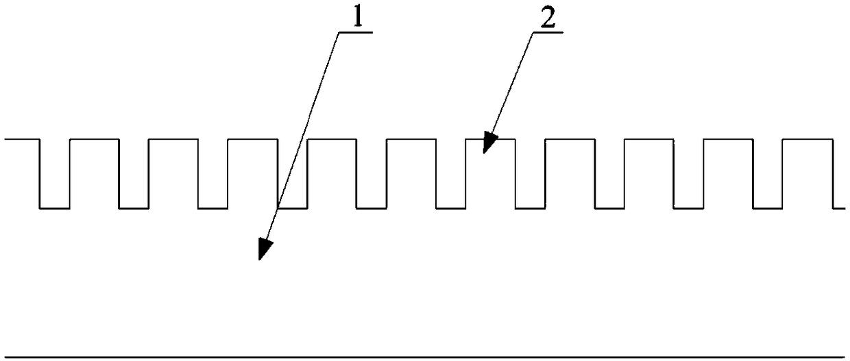
[0030] Such as Figure 1-2 As shown, a capillary core structure includes a copper substrate 1, on which a groove structure 2 arranged in parallel is arranged, and countless randomly distributed micropores 3 are formed on the surface of the groove structure. The groove depth is 0.3mm, the groove width is 0.2mm, the groove spacing is 0.5mm, and the equivalent diameter of micropores on the groove surface is 10-30μm.

[0031] The invention makes the groove also have a porous structure, and the pores are directly formed on the surface of the groove, which has stronger vibration resistance compared with sintering, and stronger capillary performance than pure grooves.

[0032] The manufacturing method of the above-mentioned capillary core structure comprises the following steps:

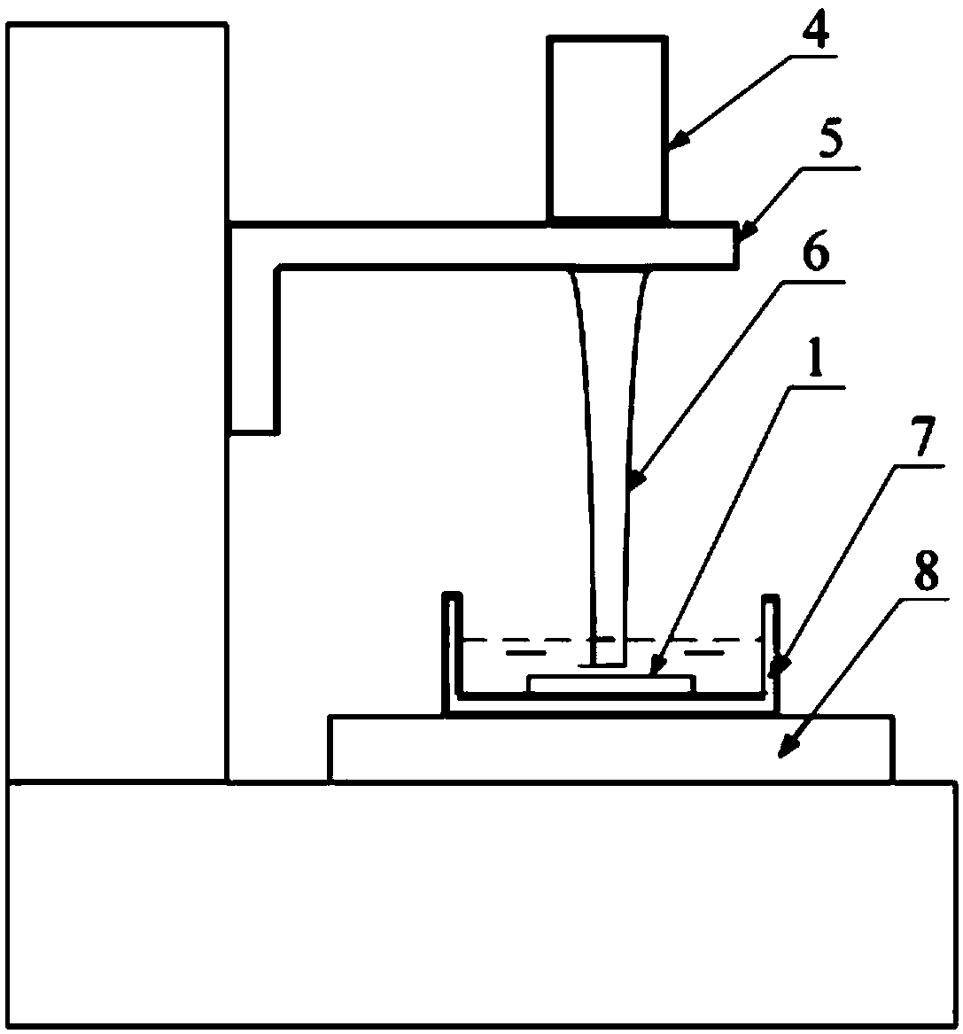
[0033] S1. Process a groove structure arranged in parallel on the surface of the copper substrate by wire cutting, and clean and dry it;

[0034] S2. Fix the processed red copper substrate on the bottom o...

Embodiment 2

[0037] A porous groove capillary core structure includes an aluminum base plate, on which a groove structure arranged in parallel is arranged, and countless randomly distributed micropores are formed on the surface of the groove structure. The groove depth is 0.7mm, the groove width is 0.5mm, the groove spacing is 0.7mm, and the equivalent diameter of micropores on the groove surface is 10-30μm.

[0038] The manufacturing method of the above-mentioned porous groove capillary core structure includes the following steps:

[0039] S1. Process a groove structure arranged in parallel on the surface of the aluminum substrate by milling, and clean and dry it;

[0040] S2. Fix the processed aluminum substrate on the bottom of the container containing pure water, the groove structure faces upward and the liquid level of the pure water is higher than the top surface of the groove, and the distance between the liquid surface of the pure water and the top surface of the groove is 15mm;

...


PUM

PropertyMeasurementUnit
diameteraaaaaaaaaa

Abstract

The invention discloses a preparation method of a capillary core structure and further discloses the capillary core structure. The preparation method comprises the steps that groove structures arrayedin parallel are machined in the surface of a metal base board; and the surfaces of the grooves are subjected to cavitation erosion through liquid vibrating along with ultrasonic waves, and microcellular structures distributed at random are formed. The capillary core structure comprises the metal base board and the groove structures arrayed in parallel in the base board; and the multiple micropores distributed at random are formed in the surfaces of the groove structures. The capillary core structure is directly formed on the surfaces of the grooves, so that the capillary suction for working media is effectively enhanced, the lubrication area is increased, much more nucleate boiling points are provided, and the structure has the excellent impact resistance. The capillary core structure isapplied to flat board heat pipes and can promote rapid returning and re-boiling of condensation working media, and the heat transfer performance of the flat board heat pipes and the stability under the vibration working condition are enhanced.

Description

technical field [0001] The invention relates to the technical field of flat heat pipe manufacture, in particular to a porous groove capillary core structure with strong vibration resistance and a preparation method. Background technique [0002] With the development of electronic technology, heat pipes have become the main means to solve the problem of thermal control of high-density heat flow electronic devices. They have the advantages of high thermal conductivity, good temperature uniformity, long transmission distance, and long life. The capillary core structure of the heat pipe provides the main driving force for the reflux of the condensed working fluid in the heat pipe, and at the same time provides a larger heat transfer area and more boiling core sites for the boiling of the working fluid, which is of great significance to the excellent heat transfer performance of the heat pipe. As the size of electronic components is decreasing, the operating frequency is getting ...

Claims


Application Information

Patent Timeline
Patent Type & Authority Applications(China)
IPC IPC(8): F28D15/04
CPCF28D15/046
Inventor 钟桂生汤勇丁鑫锐李宗涛陈恭范东强聂聪
Owner SOUTH CHINA UNIV OF TECH
Why Eureka
Try Eureka