
Vapour chamber evaporation imbibition core of fractal groove-hole structure and manufacturing method

A manufacturing method and technology for a soaking plate, applied in the field of heat transfer, can solve the problems of complicated execution steps, expensive equipment, small capillary radius, etc., and achieve the advantages of simple and easy technical means, low equipment cost investment, and increased specific surface area. Effect

Active Publication Date: 2015-06-03
SOUTH CHINA UNIV OF TECH
View PDF5 Cites 0 Cited by
  • Summary
  • Abstract
  • Description
  • Claims
  • Application Information

AI Technical Summary

Problems solved by technology

However, the capillary radius of these structures is small, the flow resistance is large, easy to be blocked and the permeability is low.
At the same time, the above methods have disadvantages such as expensive equipment required, complicated execution steps, time-consuming and labor-intensive production, and uncontrollable shape of the slot-hole structure.
Although the disadvantages of the above-mentioned processing methods can be overcome by means of mechanical processing, and the groove-hole structure processed by the current machine has high permeability and low flow resistance, but it also has low capillary suction and low enhanced boiling performance. Different types of processing technology and other defects

Method used


Image

  • Vapour chamber evaporation imbibition core of fractal groove-hole structure and manufacturing method
  • Vapour chamber evaporation imbibition core of fractal groove-hole structure and manufacturing method
  • Vapour chamber evaporation imbibition core of fractal groove-hole structure and manufacturing method

Examples


Embodiment

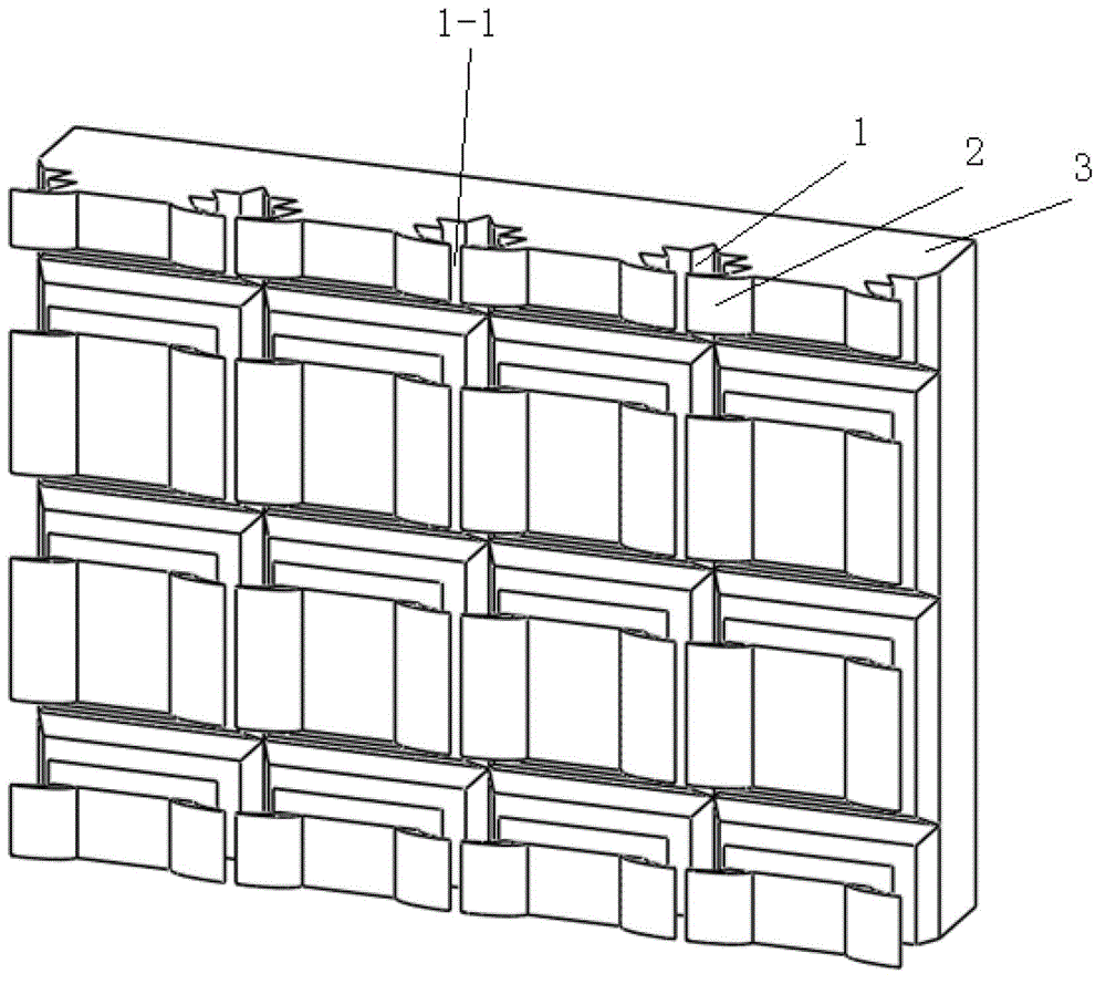
[0031] Such as figure 1 shown. The vapor chamber evaporating liquid-absorbing wick with a fractal groove-hole structure of the present invention includes an evaporation plate 3, fractal grooves 1 are distributed along the longitudinal and transverse arrays of the evaporation surface of the evaporation plate, and fins 2 are arranged on the groove top of the fractal groove, Rectangular slits 1-1 with semi-closed rectangular openings are formed between the fins, and the fractal groove 1 is composed of multiple V-shaped grooves. The distance between the fractal grooves 1 is 2.96mm-4mm; the depth of the V-shaped grooves on both sides of the fractal grooves 1 is 0.26mm-0.49mm, and the depth of the V-shaped grooves at the bottom of the fractal grooves 1 is 0.5mm~1.3mm.

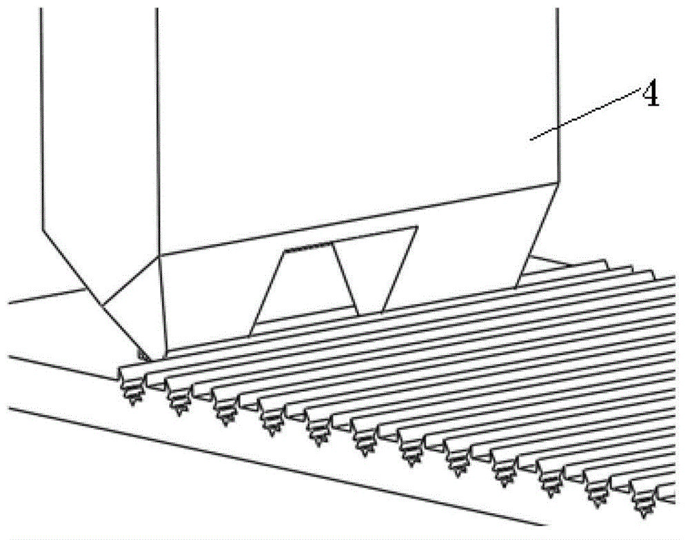
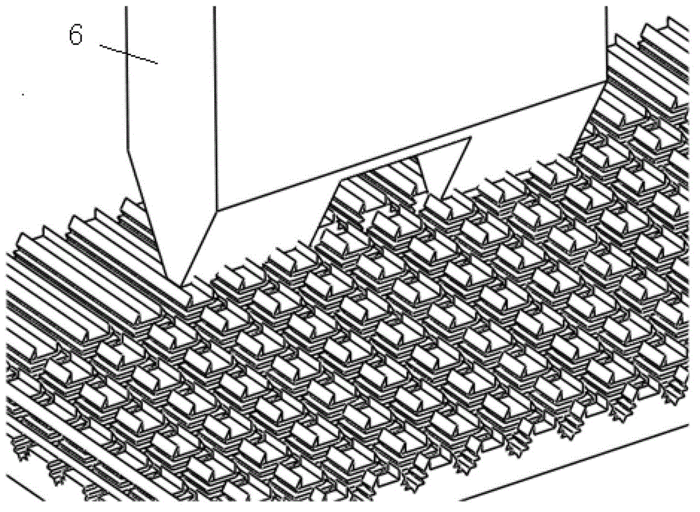
[0032] Such as Figure 2 ~ Figure 6 shown. The above-mentioned manufacturing method of vapor chamber evaporative liquid-absorbing core with fractal groove-hole structure can be realized through the following step...


PUM


Abstract

The invention discloses a vapour chamber evaporation imbibition core of a fractal groove-hole structure and a manufacturing method. The evaporation imbibition core comprises an evaporation plate and fractal grooves, wherein the fractal grooves are distributed in an array mode in the longitudinal direction and the transverse direction of the evaporation face of the evaporation plate, and a slit structure of semi-closed rectangular openings formed by fins is arranged on the tops of the fractal grooves. The manufacturing process comprises the steps of screening a substrate, fixing burrs on a jaw vice of a facing machine after the burrs are processed, and conducting leveling; using a second-order composite fractal plough cutter for machining longitudinally-distributed fractal groove arrays on the surface of the substrate, then, rotating the substrate by 90 degrees in a clockwise mode, then, using a second-order composite fractal planing cutter for machining transversely-distributed fractal groove arrays, forming the two fins on the top of each fractal groove, then rotating the substrate by 90 degrees in an anticlockwise mode, and using a ball-head forming cutter for squeezing the fins in the direction of a groove opening of each fractal groove. With the structure, the specific surface area of the evaporation face is increased, nucleation is facilitated, capillary attraction and poriness of the evaporation face of a vapour chamber are improved, and further a role in strengthening pool boiling is played.

Description

technical field [0001] The invention relates to the field of heat transfer, in particular to a vapor chamber evaporation liquid-absorbing core with a fractal groove-hole structure and a manufacturing method. Background technique [0002] The field of optoelectronics is a key area for the development of science and technology and the improvement of people's living standards in the 21st century. For example, Light Emitting Diode (LED for short) technology has the advantages of energy saving, environmental protection and long life, and is recognized as the fourth-generation lighting source. But thermal problems are becoming more and more serious with the development of optoelectronics field. At present, the power consumption of LED array light sources exceeds 100W, and the heat flux density of high-power LED chips has reached 2×10⁶W / M2. Such a high heat flux can create fatal thermal problems if not channeled effectively. [0003] The vapor chamber is a phase change heat tran...

Claims


Application Information

Patent Timeline
Patent Type & Authority Patents(China)
IPC IPC(8): F28D15/04B23P15/26
Inventor 汤勇万珍平陆龙生袁伟彭洁旻陈维付婷
Owner SOUTH CHINA UNIV OF TECH
Learn More