Throttling device for air conditioner check valve

A throttling device and one-way valve technology, applied in the direction of valve devices, control valves, functional valves, etc., can solve the problems of reducing the heating effect of air conditioners and reducing the heating capacity, so as to reduce power consumption and improve heating capacity , the effect of increasing the cooling capacity

Inactive Publication Date: 2012-08-15
苏州恒兆空调节能科技有限公司
View PDF5 Cites 12 Cited by
  • Summary
  • Abstract
  • Description
  • Claims
  • Application Information

AI Technical Summary

Problems solved by technology

Despite the above advantages, the specific use of this air conditioner nozzle throttling device still has the following problems: During the heating process of the air conditioner (refrigeration reverse cycle), the high-pressure liquid refrigerant is output from the evaporator, and is throttled by the nozzle. The small hole of the flow device is sprayed in reverse, and the pressure is reduced below the critical pressure. The premature vaporization reduces the heating capacity, so the heating effect of the air conditioner is greatly reduced.

Method used


Image

  • Throttling device for air conditioner check valve
  • Throttling device for air conditioner check valve
  • Throttling device for air conditioner check valve

Examples


Embodiment 1

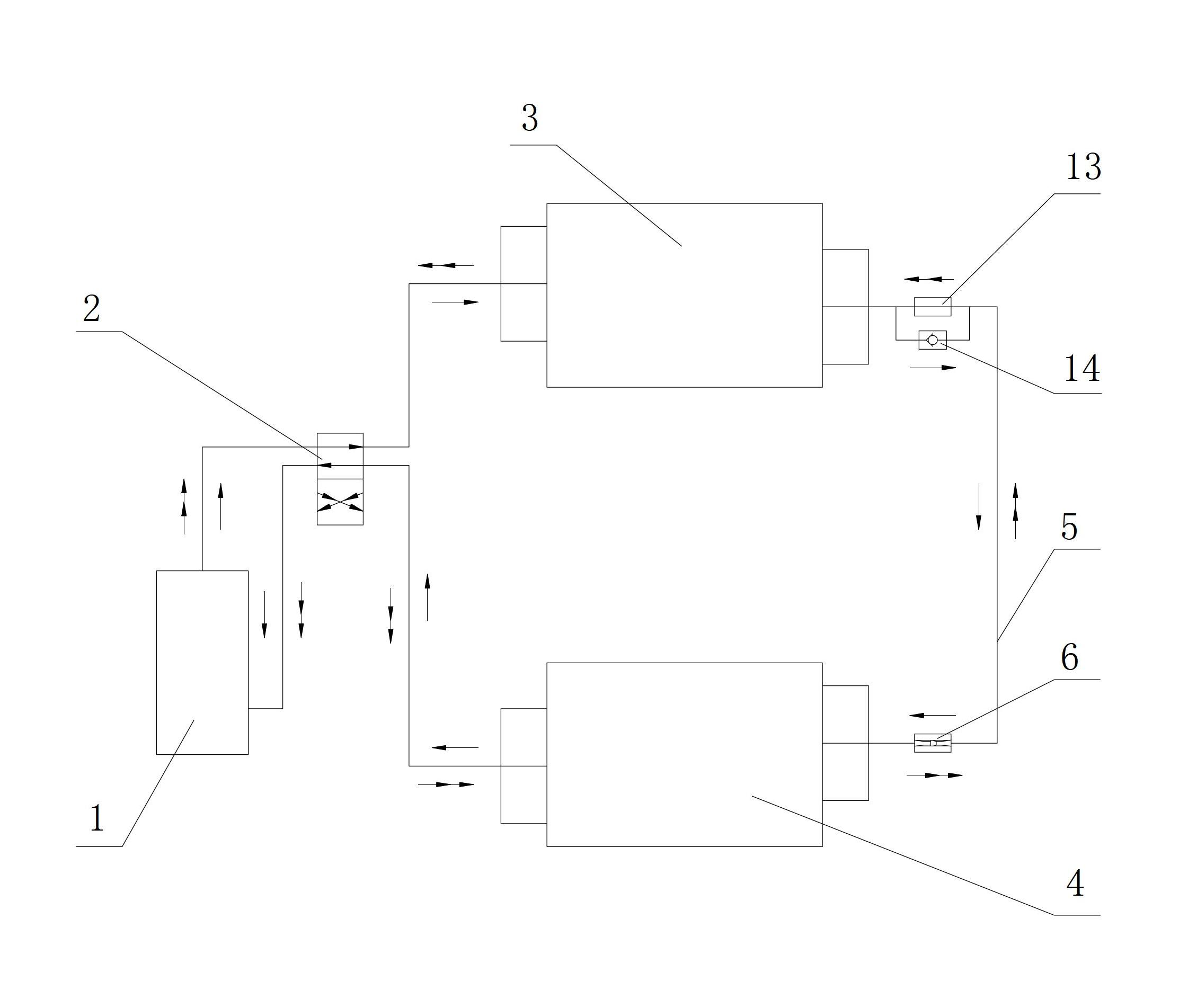
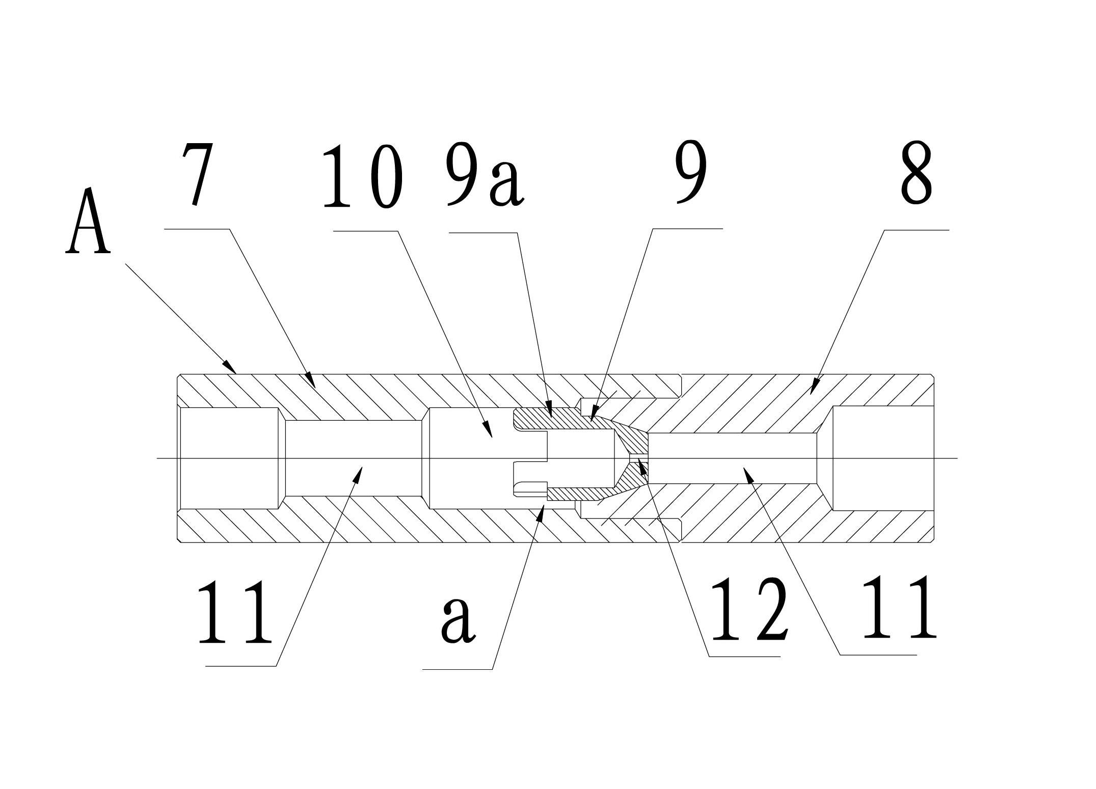
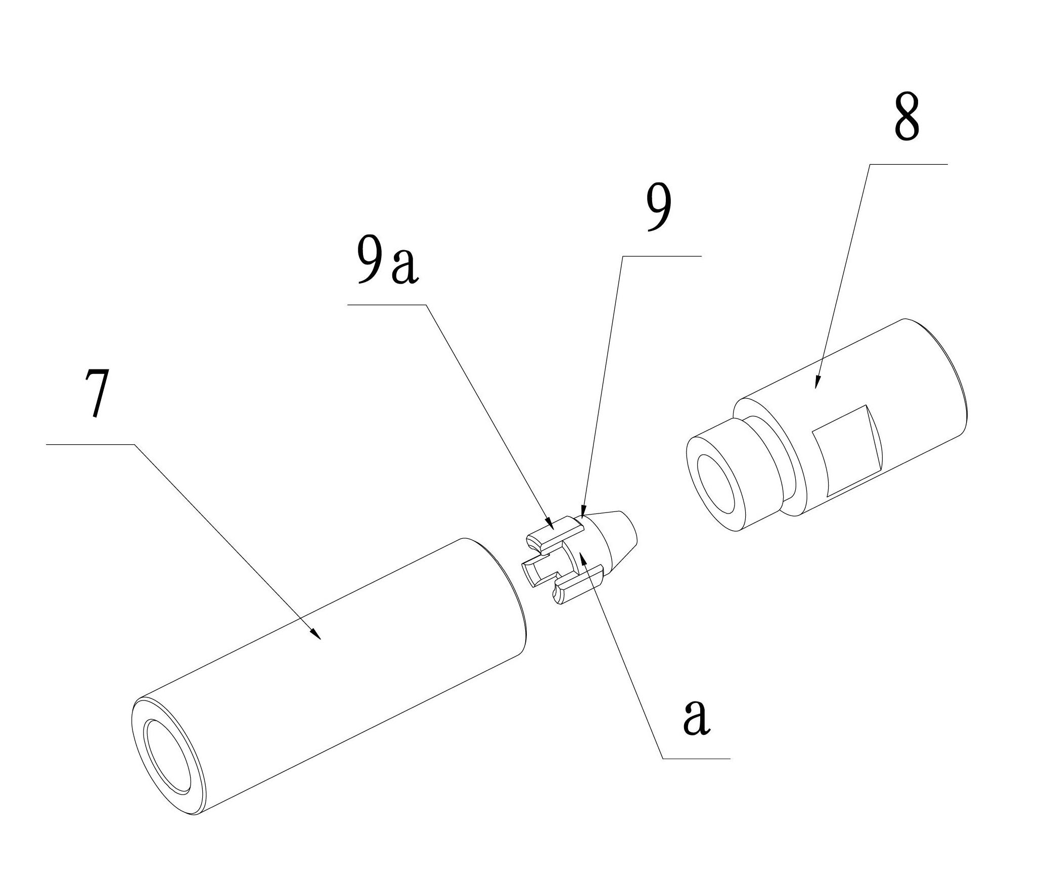
[0026] Embodiment 1: as figure 1 Shown is a structural schematic diagram of a specific embodiment of the one-way valve throttling device of the air conditioner provided by the present invention. Like a conventional air conditioner, it has a compressor 1, a four-way valve 2, The condenser 3 and the evaporator 4, and on the delivery pipe 5 connecting the condenser 3 and the evaporator 4, a heating throttling device is provided near the end of the condenser 3. In this embodiment, the heating throttling device is a capillary tube joint A flow device 13, and a check valve 14 is connected in parallel on the capillary restrictor 13; and a cooling throttling device is provided near the end of the evaporator 4, and the cooling throttling device is a check valve device 6 with a throttling function, and The conduction direction of this non-return valve device 6 with throttling function points to the condenser 3 .

[0027] Concrete combination figure 2 , image 3 As shown, the one-way...

Embodiment 2

[0043] Embodiment 2: as Figure 4 Shown is another specific embodiment of the air conditioner check valve throttling device of the present invention, its structure is basically the same as that of embodiment 1, the difference is that the cooling throttling device near the end of the evaporator 4 is three parallel connections The one-way valve device 6 with throttling function, the aperture parameters of the capillary orifice 12 in the three one-way valve devices 6 with throttling function are respectively selected as 0.59mm, 0.61mm, 0.65mm, and the throttle length is also That is, the hole lengths of the fine detail orifices 12 are all 4mm. The working principle and method of this embodiment can be referred to Embodiment 1, so it will not be described in detail.

[0044] Further illustrate the remarkable effect of the present invention with actual test data comparison below:

[0045] 1. Test model: a split-type air conditioner with a cooling capacity of 3500 W.

[0046] 2. ...


PUM


Abstract

The invention discloses a throttling device for an air conditioner check valve, which comprises a compressor, a four-way valve, a condenser and an evaporator, wherein the compressor, the four-way valve, the condenser and the evaporator are communicated circularly by pipelines, and a conveying pipeline for connecting the condenser and the evaporator is provided with a refrigeration throttling device close to the evaporator. The throttling device is characterized in that the refrigeration throttling device is one or more parallel check valve devices with a throttling device, and the conduction direction of the throttling device with the throttling function is appointed to the condenser. Therefore, the throttling device with the throttling function has the function and the advantage of a nozzle throttle and the check valve, so that the cooling capability of the condenser is improved when the air conditioner is under the refrigeration working state, the refrigeration amount of the air conditioner is increased, and the power consumption of the air conditioner is lowered; when the air conditioner is under the heating working state, high-pressure liquid refrigerant output by the evaporator is prevented from quickly vaporizing so as to lower heating amount to improve the heating capability of the air conditioner; and the air conditioner is guaranteed to avoiding two-phase flow noise in the refrigerating and heating process.

Description

technical field [0001] The invention relates to a one-way valve throttling device of an air conditioner. Background technique [0002] Existing traditional air conditioners usually consist of a compressor connected by a delivery pipeline, a four-way valve, a condenser, a capillary restrictor, a one-way valve and an evaporator. The high-temperature and high-pressure gaseous refrigerant output by the compressor enters the condenser through the four-way valve, and exchanges heat with the outdoor environment. When it is cooled below the critical temperature, the refrigerant is condensed from gaseous state to liquid state; the liquid refrigerant is decompressed and vaporized through the capillary restrictor. After decompression and vaporization, the gas-liquid mixed-flow refrigerant enters the evaporator through the delivery pipe, and exchanges heat with the indoor environment to realize refrigeration; then passes through the four-way valve, is sucked by the compressor, and enter...

Claims


Application Information

Patent Timeline
Patent Type & Authority Applications(China)
IPC IPC(8): F25B41/06F16K15/02
Inventor 赵军朱宁远蒋文格王海涛
Owner 苏州恒兆空调节能科技有限公司
Why Eureka
Try Eureka