Low-temperature removing method of CO2 in natural gas and natural gas liquefying device adopting method

A technology for low-temperature removal and liquefaction device, applied in the field of low-temperature removal of CO2 in natural gas and natural gas liquefaction device, can solve problems such as corrosion, and achieve the effects of improving economy, less side reactions, and simple and efficient process

Inactive Publication Date: 2012-08-15
贾林祥
View PDF8 Cites 7 Cited by
  • Summary
  • Abstract
  • Description
  • Claims
  • Application Information

AI Technical Summary

Problems solved by technology

[0010] The invention provides a CO in natural gas 2 The low-temperature removal method and the natural gas liquefaction device using th

Method used


Image

  • Low-temperature removing method of CO2 in natural gas and natural gas liquefying device adopting method
  • Low-temperature removing method of CO2 in natural gas and natural gas liquefying device adopting method

Examples


specific Embodiment approach 1

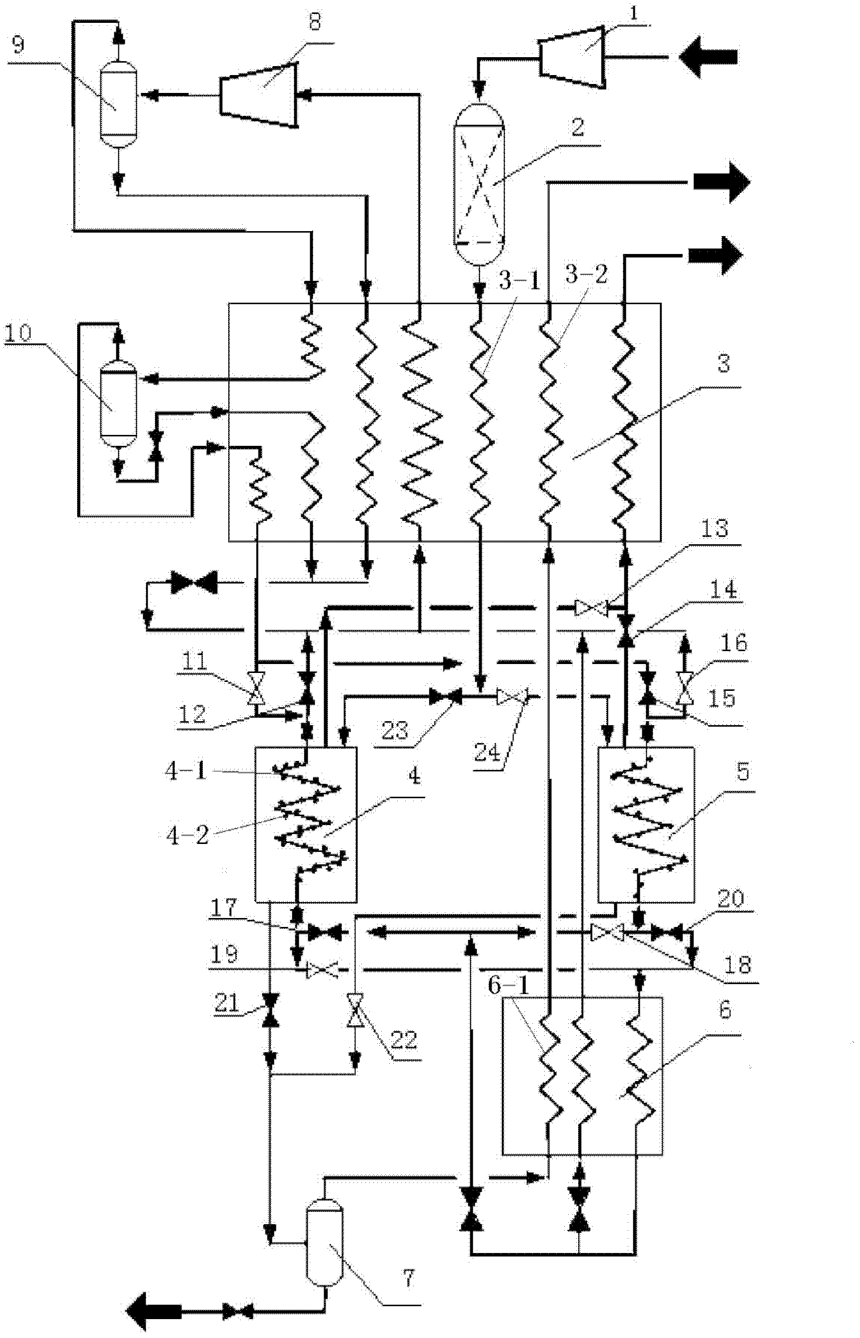
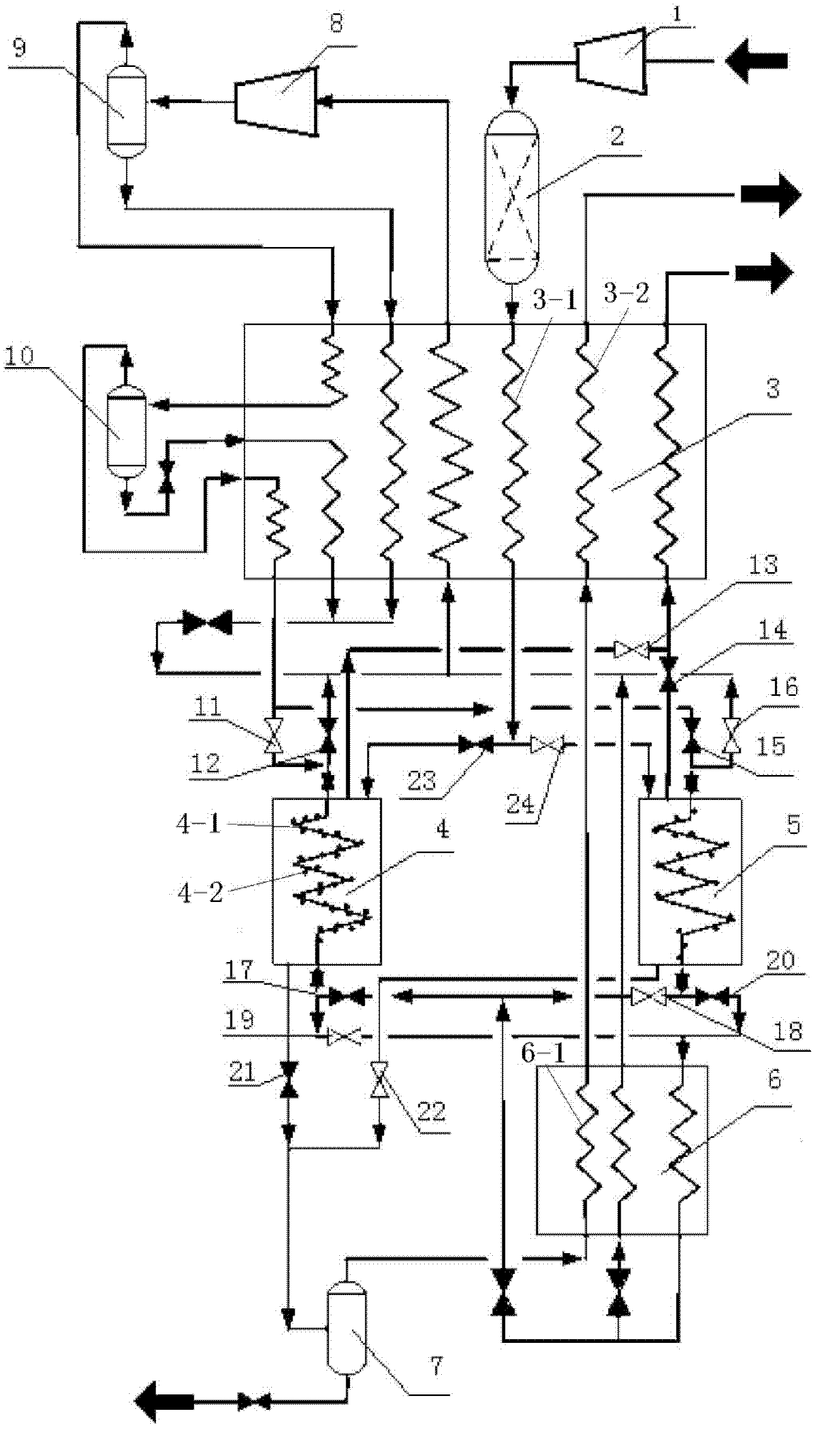
[0022] Specific Embodiment 1: The present embodiment will be specifically described below with reference to FIG. 1 . CO in natural gas 2 The low-temperature removal method includes the following steps: 1. Compressing natural gas with a natural gas compressor 1; 2. Dehydrating and drying the natural gas with a natural gas dehydration drying tower 2; 3. Precooling the natural gas with a pre-cooling heat exchanger 3; Four, use the refrigeration heat exchanger 4 to freeze the natural gas, so that the CO in the natural gas 2 Frozen into a solid state and adhered to and fixed in the freezing chamber; 5. The natural gas is discharged from the freezing chamber, thereby obtaining the removal of CO 2 of natural gas.

specific Embodiment approach 2

[0023] Specific Embodiment 2: The present embodiment will be specifically described below with reference to FIG. 1 . The difference between this embodiment and Embodiment 1 is that it also includes step 6, raising the temperature in the freezing cavity of the freezing heat exchanger 4, so as to freeze into solid CO 2 Converted to gas discharge. able to obtain CO 2 gas.

specific Embodiment approach 3

[0024] Specific Embodiment Three: The present embodiment will be specifically described below with reference to FIG. 1 . This embodiment applies CO in natural gas 2 The natural gas liquefaction device of the low-temperature removal method, which includes a refrigeration cycle system, and it also includes a natural gas compressor 1, a natural gas dehydration drying tower 2, a pre-cooling heat exchanger 3 and a freezing heat exchanger 4, and the refrigeration cycle system is a pre-cooling heat exchange Device 3 and refrigerating heat exchanger 4 provide the cooling capacity of refrigeration, the inlet of natural gas compressor 1 is used as the inlet of natural gas, the outlet of natural gas compressor 1 is connected with the natural gas inlet of dehydration drying tower 2, and the natural gas outlet of dehydration drying tower 2 is connected with pre-heater One end of the heat exchange coil 3-1 in the cold heat exchanger 3, the other end of the heat exchange coil 3-1 is connecte...


PUM


Abstract

The invention provides a low-temperature removing method of CO2 in natural gas and a natural gas liquefying device adopting the method. The invention relates to a purifying method and a liquefying device of the natural gas, which are used for removing the CO2 in the natural gas and solve the problems that a chemical absorption method for removing the CO2 needs to use a chemical agent so that a common corrosion problem exists. The method comprises the following steps of: compressing the natural gas; dehydrating, drying and pre-cooling the natural gas; freezing the natural gas and freezing the CO2 into a solid state and attaching, so as to remove the natural gas of the CO2. The device comprises a refrigerating circulation system, a natural gas compressor, a natural gas dehydrating and drying tower, a pre-cooling heat exchanger and a freezing heat exchanger; an inlet of the natural gas compressor is used as the inlet of the natural gas and an outlet of the natural gas compressor is communicated with the other end of a heat exchange coil pipe in the pre-cooling heat exchanger through the dehydrating and drying tower; and the other end of the heat exchange coil pipe is communicated with one end of a shell side of the freezing heat exchanger and the other end of the shell side of the freezing heat exchanger is used as a discharging end of the liquefied natural gas.

Description

Technical field: [0001] The invention relates to a purification method and a liquefaction device of natural gas, in particular to CO 2 The low-temperature removal method and the natural gas liquefaction device using the method. Background technique: [0002] Since the origin of natural gas is often relatively remote, especially offshore natural gas, transportation and storage problems must be solved. The temperature of liquefied natural gas is generally 112K, its density is more than 600 times that of methane under standard conditions, and its volumetric energy density is 72% of petroleum, which is very conducive to storage and transportation. In order to prevent impurities from corroding equipment during storage and transportation and freezing at low temperatures to block equipment and pipelines, natural gas must be pretreated to remove impurities. [0003] For the decarbonization of natural gas, many methods have been proposed at home and abroad, basically including phys...

Claims


Application Information

Patent Timeline
IPC IPC(8): F25J3/08C10L3/10
CPCF25J1/0022F25J1/0055F25J1/0212F25J1/0267F25J1/0265F25J2205/24F25J2205/20F25J2220/66F25J1/004
Inventor 贾林祥
Owner 贾林祥
Why Eureka
Try Eureka