
Toy trench mortar as well as cannonball and pressure spring barrel thereof

A technology for mortars and toys, which is applied in the field of toy mortars and their shells and compression springs, can solve the problems of unsuitable ejection of shells, lack of fun, hidden safety hazards, etc., and achieve realistic and beautiful flying posture, intuitive and visible flight process, Mitigates the effects of impact and scratches

Active Publication Date: 2012-08-15
付辉
View PDF6 Cites 18 Cited by
  • Summary
  • Abstract
  • Description
  • Claims
  • Application Information

AI Technical Summary

Problems solved by technology

[0002] Most of the existing toy mortars are scaled-down simulation models and cannot be used for launching operations. The patents of individual mortar toys that can be launched are insufficient in terms of interest due to factors such as structure and launching methods. , there are great hidden dangers in terms of safety
In the patent 92245987.8, the patentee provides a toy of a mortar and a shell, the bullet of which is a streamlined thin-shell bullet, which is easy to cause damage to the player's face, especially the eyes; The inserted compression spring rod will pose a safety hazard when children hold it for playing and running; the rear section of the barrel and the breech of the gun are set as a closed structure, and the toy shell is of a lightweight structure. When filling from the muzzle, the air in the tube Under pressure, it is not easy to discharge, which weakens the downward speed of the shell, and it is easy to cause failure to fire. When ejecting, a negative pressure is formed at the rear of the shell, making it difficult for the shell to eject. Even if the spring force is strengthened, the strong spring will make the shell structure weight increase, affect the flight attitude, and make the operation difficult for children, or even unusable

Method used


Image

  • Toy trench mortar as well as cannonball and pressure spring barrel thereof
  • Toy trench mortar as well as cannonball and pressure spring barrel thereof
  • Toy trench mortar as well as cannonball and pressure spring barrel thereof

Examples


Embodiment Construction

[0031] Below in conjunction with accompanying drawing and specific embodiment the present invention is described in further detail:

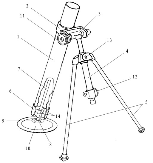
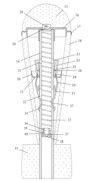
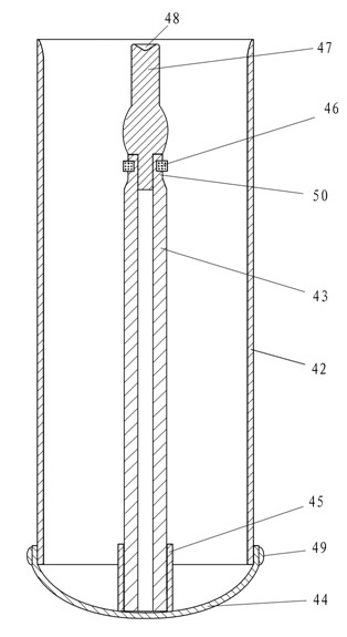
[0032] figure 1 The mortar in the middle is made of hard plastic barrel 1, gun hoop 2, direction device 3, lifter 4, leg frame 5, gun tail 6, rib plate 14, firing pin 7, gun pestle 8, and mortar 9 and seat plate 10 form. figure 2 and Figure 4 Shell in the shell is made of hard plastic core cap 16, core tube 19, sliding plug 36, reed body 21, swing arm 22, annular swing arm seat 20, limit retaining ring 34 and spring 35, Bullet 15, missile body 18 and empennage 41 that swing shaft 28, lock pin 29 and sponge or foam are made. image 3 and Figure 5 The compression spring barrel in is made up of cylinder body 42, depression bar 43, spherical cylinder bottom 44, depression bar head 47 and rubber ring 46 made of duroplastics.

[0033] Such as figure 1 As shown, a direction indicator 3 is installed on the hoop 2 at the front of the mortar barr...


PUM


Abstract

The invention relates to the field of toys, and in particular relates to a toy trench mortar as well as a cannonball and a pressure spring barrel thereof. A spring in the cannonball is firstly compressed by the pressure spring barrel, then the cannonball is filled into a toy trench mortar tube, and the spring is triggered to launch the cannonball. The trench mortar comprises a tube, a trench mortar hoop, a direction finder, a lifter, a leg frame, a trench mortar tail, a firing pin, a trench mortar pestle, a stopping mortar and a seat plate; the cannonball comprises a bullet, a cannonball body, an empennage, a bullet core cap, a bullet core pipe, the spring, a sliding plug, a swing arm, an annular swing seat and a tongue body; and the pressure spring barrel comprises a barrel body, a spherical barrel bottom, a pressing rod, a pressing rod neck, a rubber ring and a pressing rod head. The bullet, the cannonball body and the empennage of the cannonball are made of sponges or foams. The invention aims to provide a toy for simulating the appearance structure and the launching process of a military trench mortar to players.

Description

technical field [0001] The invention relates to a toy, in particular to a toy mortar and its shell and compression spring barrel. Background technique [0002] Most of the existing toy mortars are scaled-down simulation models and cannot be used for launching operations. The patents of individual mortar toys that can be launched are insufficient in terms of interest due to factors such as structure and launching methods. , there is a great hidden danger in terms of safety. In the patent 92245987.8, the patentee provides a toy of a mortar and a shell, the bullet of which is a streamlined thin-shell bullet, which is easy to cause damage to the player's face, especially the eyes; The inserted compression spring rod will pose a safety hazard when children hold it for playing and running; the rear section of the barrel and the breech of the gun are set as a closed structure, and the toy shell is of a lightweight structure. When filling from the muzzle, the air in the tube Under...

Claims


Application Information

Patent Timeline
IPC IPC(8): F42B30/10F41F1/06
Inventor 付辉
Owner 付辉
Learn More