Solar unmanned aerial vehicle

A solar unmanned aerial vehicle and a technology for unmanned aerial vehicles, which are applied in the field of unmanned aerial vehicles, can solve the problems of easily reducing the utilization efficiency of photovoltaic panels, reducing the reliability of solar backup energy, etc., so as to improve the service life, reduce damage, and improve heat dissipation capacity. Effect

Inactive Publication Date: 2021-04-09
王萍
View PDF0 Cites 1 Cited by
  • Summary
  • Abstract
  • Description
  • Claims
  • Application Information

AI Technical Summary

Problems solved by technology

[0005] Aiming at the deficiencies of the prior art, the present invention provides a solar unmanned aerial vehicle, which solves the problem that the utilization efficiency of photovoltaic panels is easily reduced and the reliability of solar backup energy is reduced when the surface of the existing solar unmanned aerial vehicle adheres to obstacles , enhanced the anti-seismic ability, can avoid the problem of easy damage to internal parts when colliding with obstacles in the air, improve the service life of the drone, enhance the heat dissipation capacity, and be able to adapt to flying for a long time and in a high temperature environment

Method used


Image

  • Solar unmanned aerial vehicle
  • Solar unmanned aerial vehicle
  • Solar unmanned aerial vehicle

Examples


Embodiment 1

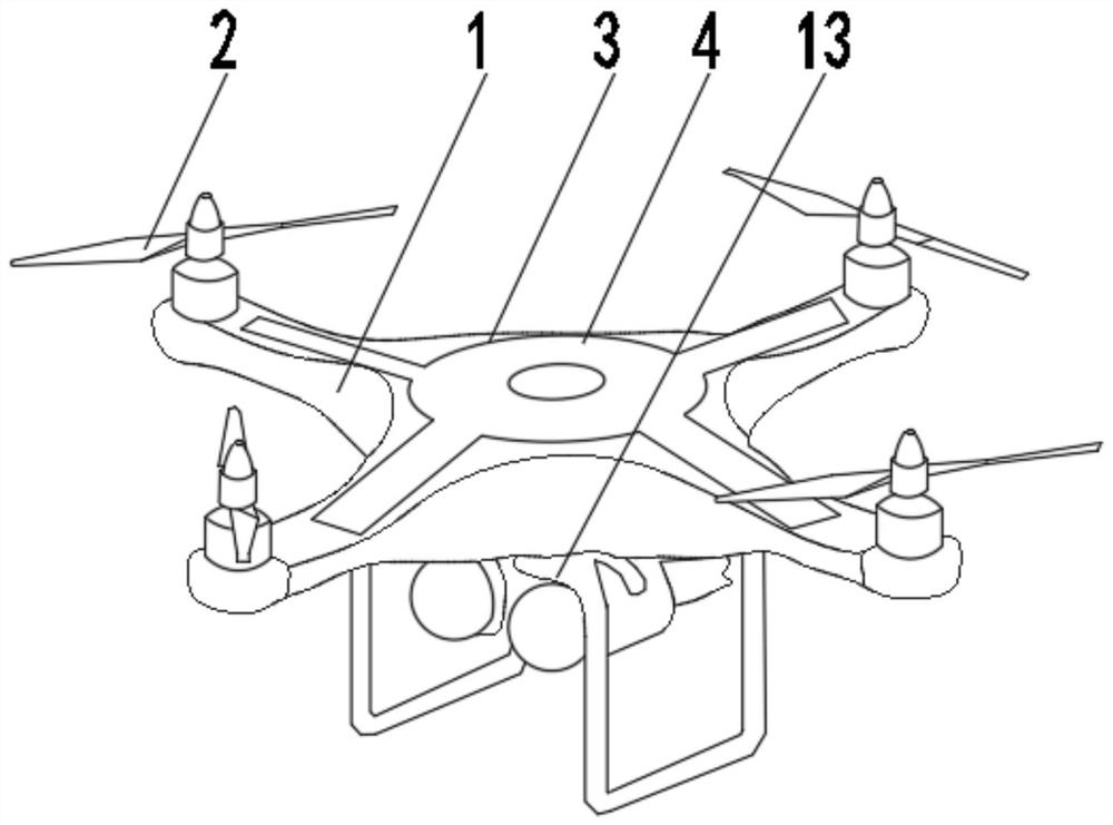
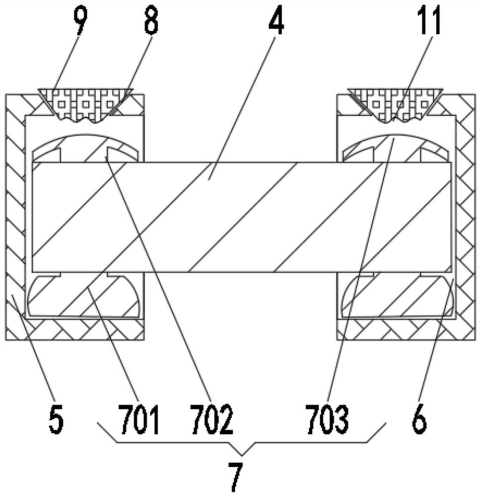
[0030]SeeFigure 1-2 The present invention provides a technical solution: a solar drone, including the drone body 1, the top symmetry of the drone main body 1, mounting the organic wing 2, the top of the drone main body 1 is opened, mounting The photovoltaic plate 4 is attached to the inside of the groove 3, and the photovoltaic plate 4 is electrically connected to the drone body 1, and both ends of the photovoltaic plate 4 are attached, and the control block 5 is opened, the control block 6, the control block is opened. 5 Turn the inner wall of the mounting groove 3, the inside of the control groove 6 is mounted, and the bottom fixed connection of the drone main body 1 has a landing gear 13.

[0031]The buffer device 7 includes a support balloon 701 that is mounted on the inner bottom portion of the control groove 6, and the top communication of the support airbag 701 is connected to the vent pipe 702, and the vent pipe 702 penetrates the photovoltaic plate 4 and extends to the photovo...

Embodiment 2

[0034]SeeFigure 1-3 The present invention provides a technical solution: On the basis of the first example, the top of the control block 5 is opened, and the lifting groove 8 is in communication with the control groove 6, and there is a lifting block 9 inside the lifting groove 8, lift block 9. The top of the 9 is attached with a heat sink 10.

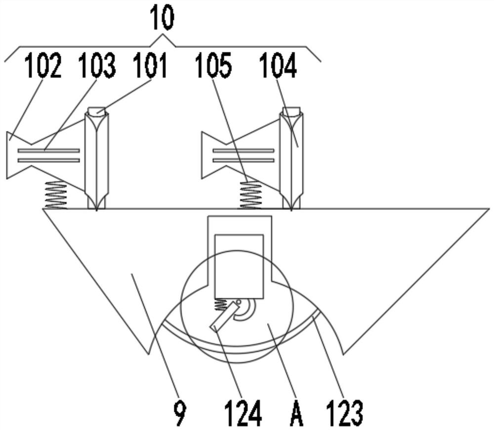
[0035]The heat sink 10 includes a heat conductive rod 101 that is rotatably coupled with a heat sink 102, and the heat sink 102 is distingurated from one end of the thermal rod 101, and a heat dissipation hole 103 is opened at the top of the heat sink 102.

[0036]The outer sleeve of the thermally conductive rod 101 is provided with a rotating collar 104, and one side of the rotating collar 104 is a tapered, and the heat sink 102 is mounted on one side of the rotating collar 104, and the bottom of the heat sink 102 passes through the reset spring 105 and the lift block 9. Secure connection.

[0037]When used, the reset spring 105 lifted the heat sink...

Embodiment 3

[0040]SeeFigure 1-5The present invention provides a technical solution: on the basis of the second embodiment, the bottom portion of the lifting block 9 is opened, and the protective device 12 is mounted inside the waveform groove 11, and the protection device 12 includes a reciprocating groove 121, and the reciprocating groove 121 The inside is mounted to the backup block 122, and the two sides of the inner wall of the wave groove 11 are fixed and the flexible soft plate 123 is fixedly connected to the backup block 122, and the reciprocating block 122 is slidably connected to the flexible soft plate 123.

[0041]The bottom portion of the backup block 122 is rotated connected to the outer bushing plate 124, and the top portion of the outer bushing 124 is fixed by the outer bushing spring 125, and the bottom portion of the backup 122 is fixed adjacent to the outer support plate 124. .

[0042]A sealing plate 14 is fixed between the inner walls of the reset groove 121, and the inside of the...


PUM


Abstract

The invention discloses a solar unmanned aerial vehicle which comprises an unmanned aerial vehicle main body, wings are symmetrically mounted at the top of the unmanned aerial vehicle main body, a mounting groove is formed in the top of the unmanned aerial vehicle main body, a photovoltaic panel is mounted in the mounting groove, the photovoltaic panel is electrically connected with the unmanned aerial vehicle main body, and control blocks are mounted at the two ends of the photovoltaic panel; and a control groove is formed in one side of each control block, and the control blocks are rotatably connected with the inner wall of the mounting groove. According to the solar unmanned aerial vehicle device, the problems that the utilization efficiency of a photovoltaic panel is reduced and the reliability of solar standby energy is reduced when obstacles adhere to the surface are solved, the shock resistance is enhanced, the problem that internal parts are prone to being damaged when the unmanned aerial vehicle collides with the obstacles in the air can be avoided, the service life of the unmanned aerial vehicle is prolonged, the heat dissipation capacity is enhanced, and the unmanned aerial vehicle can adapt to long-time flight in a high-temperature environment.

Description

Technical field[0001]The present invention relates to the field of drone, in particular a solar drone.Background technique[0002]Unmanned aircraft referred to as "drone", is a non-maniced aircraft that operates with radio remote control equipment and the self-propelled program control unit, there is no cockpit on the machine, but installs an automatic driver, program control device and other equipment, ground, The ship or the master-machine remote control station passengers trace, position, remote, telemetry, and digital transmission through radar, can take off aside as ordinary aircraft or with the help of the rocket to launch the radio remote control. When the flight is transferred, it can be automatically landed in the same way as the normal aircraft landing process, or it can be recycled with parachute or blocking through remote control, which can be used repeatedly, widely used in air reconnaissance, monitoring, communication, anti-submarine, electronic interference, etc. .[0003...

Claims


Application Information

Patent Timeline
Patent Type & Authority Applications(China)
IPC IPC(8): B64C39/02H02S20/30B64D33/10B64D45/00
CPCB64C39/02H02S20/30B64D33/10B64D45/00B64U50/19Y02E10/50
Inventor 王萍
Owner 王萍
Why Eureka
Try Eureka