Hall effect thruster with anode having magnetic field barrier

a technology of magnetic field barrier and anode, which is applied in the field of system for shaping the magnetic field, can solve the problems of increasing plume divergence, reducing propellant utilization efficiency, and increasing heat deposition in the anode, so as to reduce the sheath voltage of the anode, increase the efficiency of the thruster, and reduce the effect of the sheath voltag

Inactive Publication Date: 2006-04-13
AEROJET ROCKETDYNE INC
View PDF8 Cites 17 Cited by
  • Summary
  • Abstract
  • Description
  • Claims
  • Application Information

AI Technical Summary

Benefits of technology

[0008] The present invention provides an improved system for magnetic flux shaping in an ion accelerator with closed electron drift (Hall effect thruster or HET). The improved system comprises a novel anode-magnetic structure used to increase efficiency of the thruster. As in a typical closed electron drift plasma accelerator, the magnetic field in the channel exit region between the magnetic pole pieces is primarily radial. However, as one moves toward the upstream end of the discharge channel, there is an abrupt transition from a primarily radial magnetic field to an axially directed magnetic field. There are two primary drivers for the efficiency increase brought about by the magnetic field configuration discussed. The first is that it reduces the anode sheath voltage. Higher sheath voltages reduce the accelerating voltage and lead to increased heat deposition in the anode. The second mechanism for increased efficiency is reduced plasma oscillations due to better coupling of electrons to the anode. Plasma oscillations reduce propellant utilization efficiency and increase plume divergence which decrease performance. They also lead to higher electromagnetic emissions which are very undesirable for spacecraft integration. In another aspect of the invention, efficiency is increased by reducing the plume divergence. In disclosed embodiments of the invention, the magnetic field transition is generated and controlled by a magnetic shunt and / or additional magnetic field generating components.

Problems solved by technology

Higher sheath voltages reduce the accelerating voltage and lead to increased heat deposition in the anode.
Plasma oscillations reduce propellant utilization efficiency and increase plume divergence which decrease performance.
They also lead to higher electromagnetic emissions which are very undesirable for spacecraft integration.

Method used


Image

  • Hall effect thruster with anode having magnetic field barrier
  • Hall effect thruster with anode having magnetic field barrier
  • Hall effect thruster with anode having magnetic field barrier

Examples


Embodiment Construction

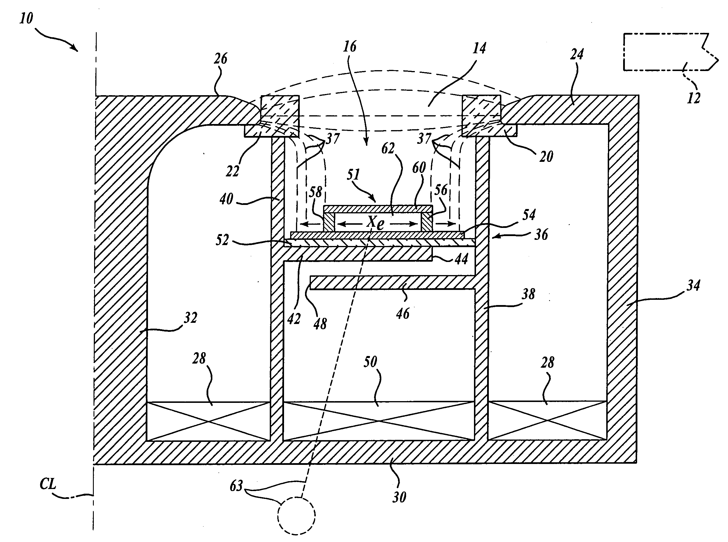
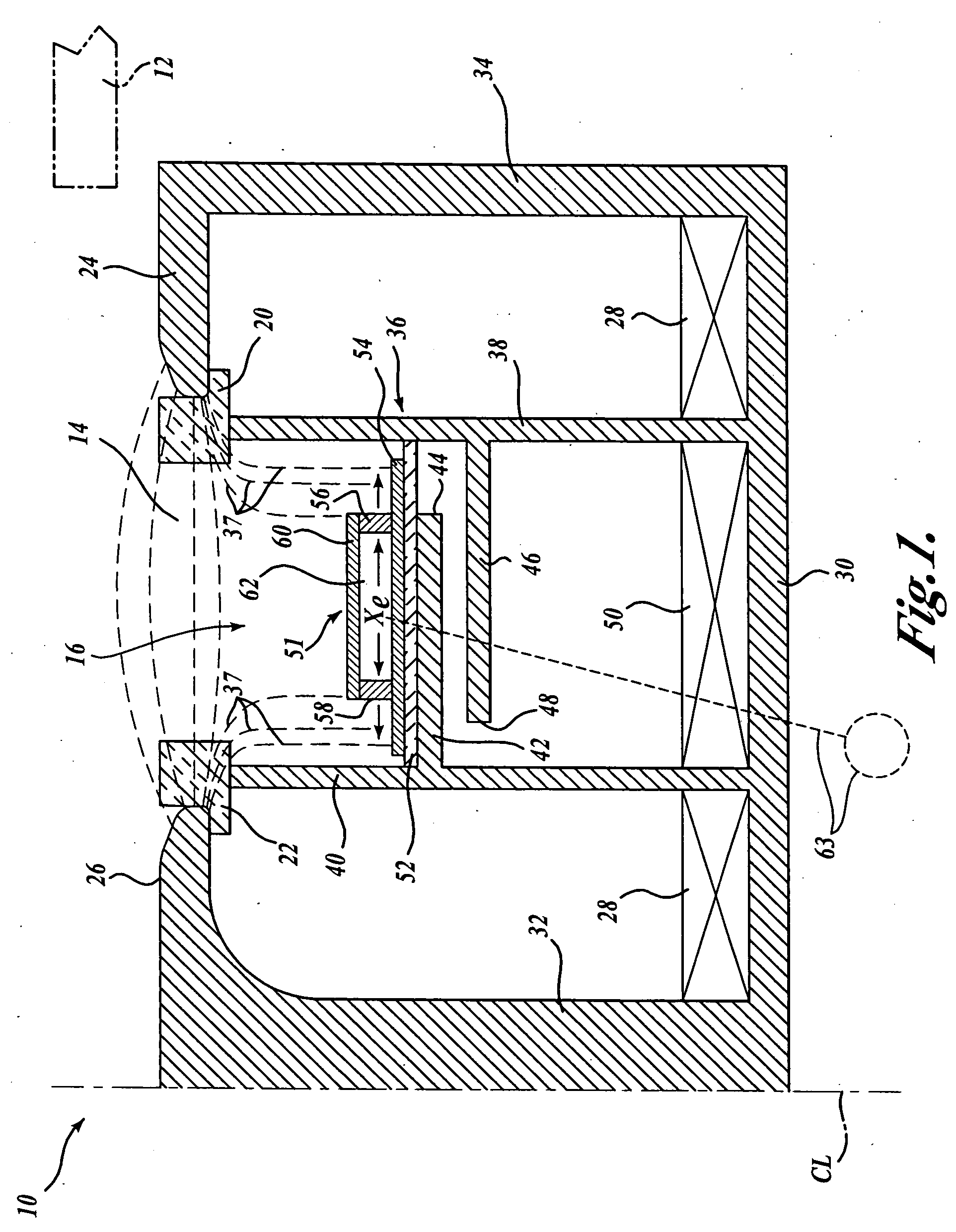
[0014]FIG. 1 illustrates a representative Hall effect thruster (HET) 10 in accordance with the present invention, it being understood that the parts are shown diagrammatically and the dimensions exaggerated for ease of illustration and description. HET 10 has a magnetic structure which is a body of revolution about the centerline CL. In general, electrons are emitted by a cathode 12 for migration toward the exit end 14 of the annular discharge channel 16. The exit end 14 of the endless annular ion formation and discharge channel 16 is formed between an outer ceramic ring or insulator 20 and an inner ceramic ring or insulator 22. The ceramic preferably is electrically insulative, and sturdy, light, and erosion resistant. It is desirable to create an essentially radially-directed magnetic field in the exit area, between an outer ferromagnetic pole piece 24 and an inner ferromagnetic pole piece 26. In the illustrated embodiment, this is achieved by flux-generating coils 28, which may b...


PUM


Abstract

An efficiency enhancing anode-magnetic structure of a Hall effect thruster produces a radially directed magnetic field between inner and outer poles at the exit portion of a gas distribution channel. The field-shaping structure includes magnetic material extending alongside the channel with an associated secondary flux-generating component to create an axially directed magnetic field in the area between the anode of the thruster and the exit portion of the gas distribution channel.

Description

CROSS-REFERENCE TO RELATED APPLICATION [0001] This application claims the benefit of U.S. Provisional Patent Application No. 60 / 322,560, filed Sep. 10, 2001.FIELD OF THE INVENTION [0002] The present invention relates to a system for shaping the magnetic field in an ion accelerator with closed drift of electrons, i.e., a system for controlling the contour of the magnetic field lines in a direction longitudinally of the gas discharge region of the accelerator, particularly in the area leading or adjacent to the anode, upstream from the ion exit end. BACKGROUND OF THE INVENTION [0003] Ion accelerators with closed electron drift, also known as “Hall effect thrusters” (HETs), have been used as a source of directed ions for plasma assisted manufacturing and for spacecraft propulsion. Representative space applications are: (1) orbit changes of spacecraft from one altitude or inclination to another; (2) atmospheric drag compensation; and (3) “stationkeeping” where propulsion is used to coun...

Claims


Application Information

Patent Timeline
Patent Type & Authority Applications(United States)
IPC IPC(8): H01J27/02H05B31/26H01J7/24F03H1/00
CPCF03H1/0075H05H1/54
Inventor DE GRYS, KRISTI H.
Owner AEROJET ROCKETDYNE INC
Why Eureka
Try Eureka