
Method for detecting focal length of high-precision spatial aerial camera

An aerial camera and space camera technology, applied in measurement devices, instruments, etc., can solve the problems of secondary reading error, reticle line width error, light tube image plane position error, etc., to reduce errors, improve accuracy, and improve The effect of detection accuracy

Inactive Publication Date: 2012-08-15
CHANGCHUN UP OPTOTECH
View PDF2 Cites 7 Cited by
  • Summary
  • Abstract
  • Description
  • Claims
  • Application Information

AI Technical Summary

Problems solved by technology

[0011] The present invention solves the problems that the existing space camera focal length detection method adopts the magnification method to introduce the position error of the light pipe image plane, the reticle line width error and the secondary reading error, and provides a method for detecting the focal length of a high-precision space aerial camera method

Method used


Image

  • Method for detecting focal length of high-precision spatial aerial camera
  • Method for detecting focal length of high-precision spatial aerial camera
  • Method for detecting focal length of high-precision spatial aerial camera

Examples


Embodiment Construction

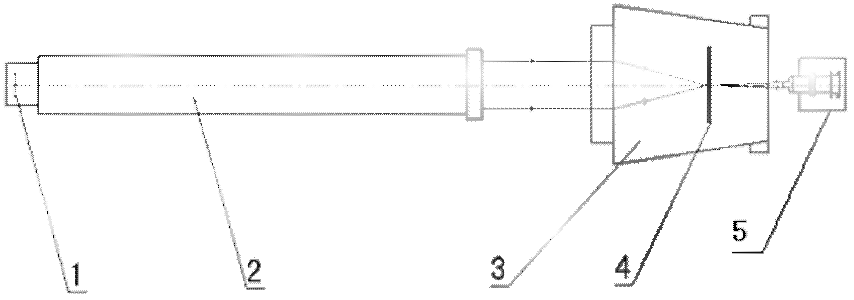
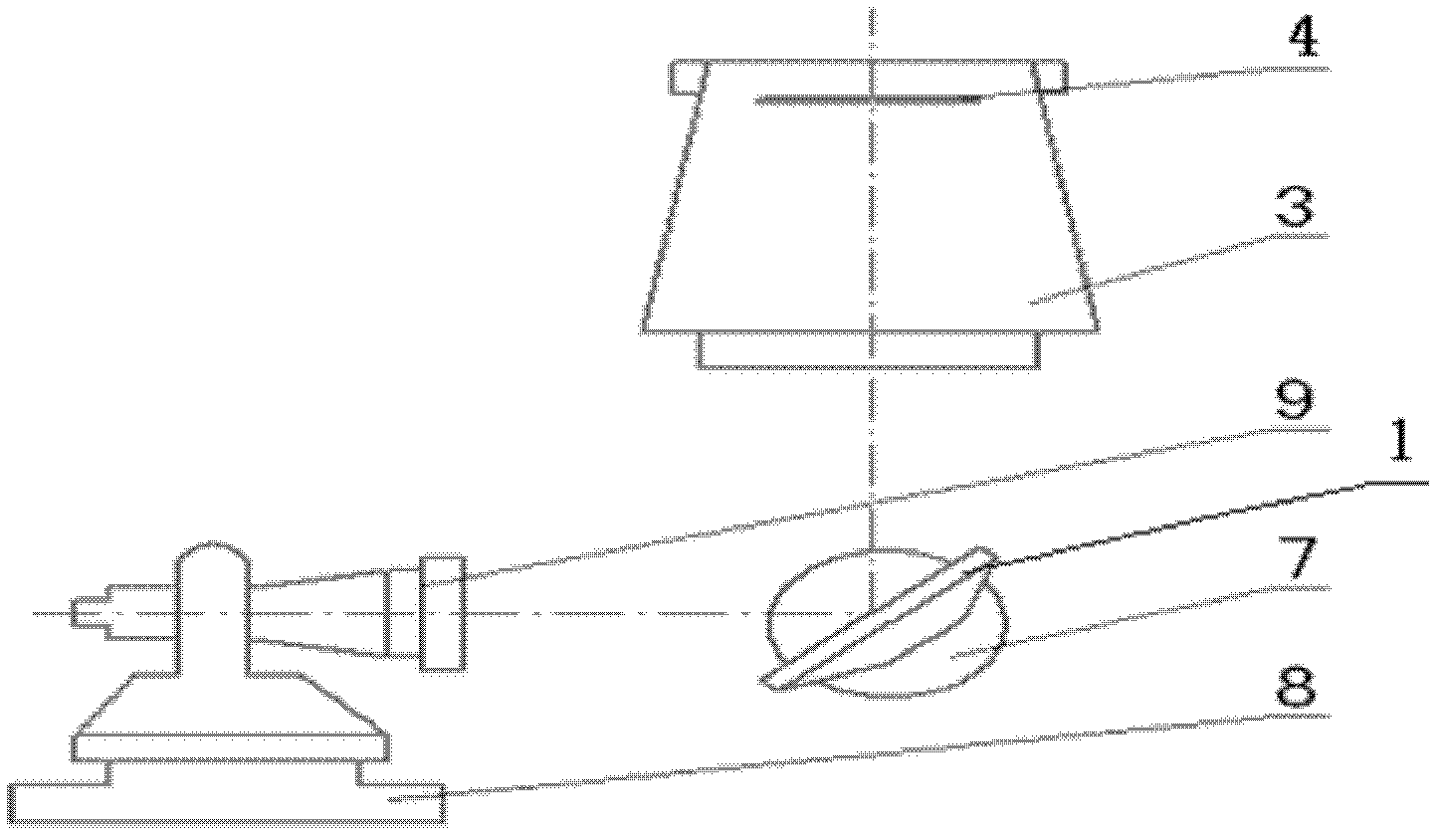
[0034] combine figure 2 and image 3 Describe the present embodiment, the method for detecting the focal length of a high-precision space aerial photography camera, the basic tool for realizing this method is: Leica theodolite, model is 5100 type, Polo plate, the line width value (standard lattice value) of described Polo plate respectively For: 2mm, 4mm, 10mm or 20mm; additional objective lens, the additional objective lens is a 3x beam expander, required to be used in combination with the Leica theodolite, the combined focal length should be at least one-half to one-fifth of the focal length of the space camera, zygo interferometer , model JPI-HR, six-dimensional adjustment frame;

[0035] The specific detection methods are as follows: 1. Use an interferometer to measure the best image plane position of the detected camera;

[0036] Since the relative aperture of space cameras is generally greater than 1 / 10, and the relative depth of focus is relatively large, and in orde...


PUM


Abstract

A method for detecting the focal length of a high-precision spatial aerial camera relates to the field of detection of optical-electro-mechanical equipment and solves the problem that an existing method for detecting the focal length of a spatial camera causes light tube image surface errors, reticle line witch errors and secondary reading errors due to factor amplification. An interferometer is used for detecting the optimal image surface position of a detected camera, a reticle is placed at the optimal image surface position of the detected camera, a theodolite loaded with an additional objective lens is used for measuring the included angle of the additional objective lens corresponding to a standard scale value of the reticle at an exit pupil position of the detected camera, and the focal length of the detected spatial camera is obtained. Detecting accuracy and detecting efficiency of the focal length of the camera are effectively improved, and the method is widely applied to the field of detection of optical-electro-mechanical equipment.

Description

technical field [0001] The invention relates to the field of optomechanical equipment detection, in particular to a method for detecting the focal length of a high-precision space aerial camera. Background technique [0002] At present, known space cameras require the measurement of the size and position of ground objects, which can be realized by processing TDI / CCD images. But the prerequisite requires precise measurement of the focal length value of the space camera optical system. [0003] The most commonly used method for detecting the focal length of a space camera is the magnification method, and its common calculation formula is expressed as: [0004] formula one [0005] In the above formula: f 光 is the focal length of the detection light pipe, X 光 is the actual lattice value of the Poirot plate of the detection light pipe, f 空 is the focal length of the detected space camera, X 空 The grid value measured for the image plane of the detected space camera; combi...

Claims


Application Information

Patent Timeline
Patent Type & Authority Applications(China)
IPC IPC(8): G01C25/00
Inventor 高云龙刘铁军李晓冰孙宝玉黄立辉张西龙
Owner CHANGCHUN UP OPTOTECH
Learn More