Multiple-inductor terminal

A multi-inductance and terminal technology, applied in the direction of transformer/inductor core, transformer/inductor coil/winding/connection, etc., can solve the problems of unstable paste and poor compatibility, achieve stable paste, improve heat dissipation efficiency, save energy cost effect

Inactive Publication Date: 2012-08-15
COIL MASTER ELECTRONICS
View PDF6 Cites 1 Cited by
  • Summary
  • Abstract
  • Description
  • Claims
  • Application Information

AI Technical Summary

Problems solved by technology

[0006] Aiming at the technical problems of unstable pasting and poor compatibility of traditional inductor terminals, the invention provides a terminal for multi-inductors

Method used


Image

  • Multiple-inductor terminal
  • Multiple-inductor terminal
  • Multiple-inductor terminal

Examples


Embodiment Construction

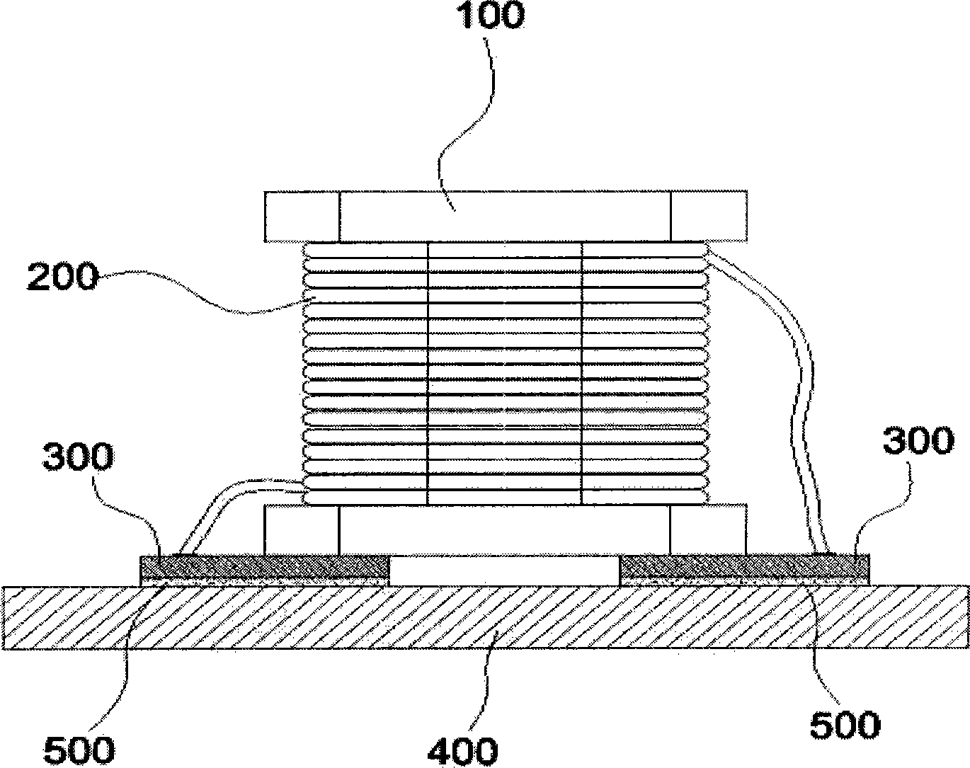
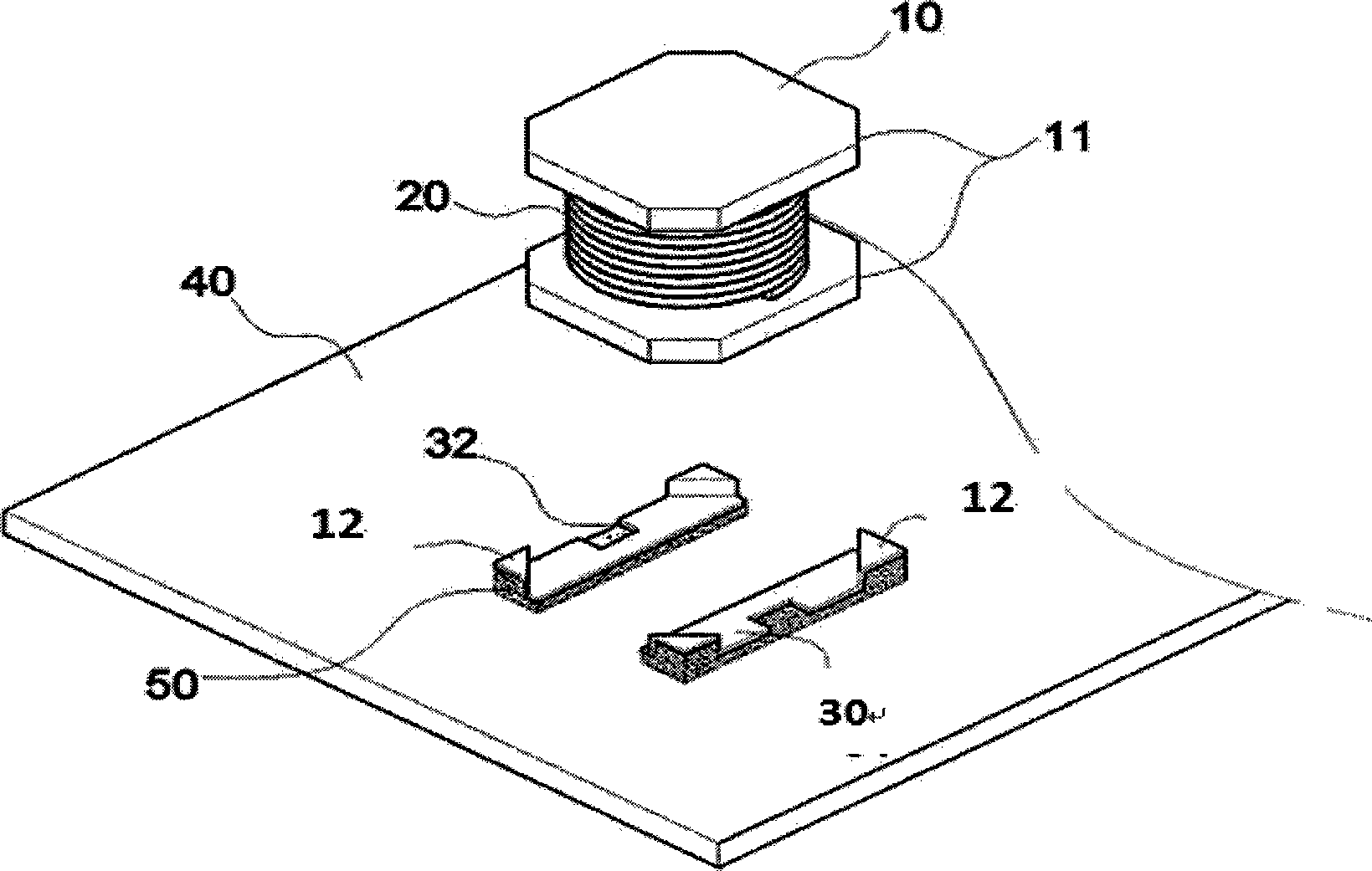
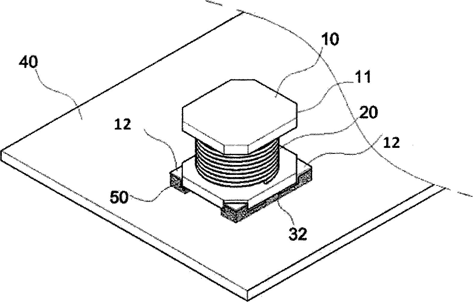
[0017] Such as Figure 2 to Figure 4 As shown, the present invention includes a magnetic core 10 and a terminal 30 wrapped with a copper wire 20, the copper wire 20 is connected to the terminal 30, the upper part of the outer end of the terminal 30 is a protrusion 12, and the bottom surface of the lower part of the magnetic core 10 is connected to the surface of the terminal 30, The lower portion of the magnetic core 10 is provided with a surface 11 that engages with the inner side of the protrusion 12 of the terminal 30 . In the actual installation process, the bottom surface of the magnetic core 10 is glued to the surface of the terminal 30, the side surface 11 of the magnetic core 10 is glued to the inner side of the protrusion 12 of the terminal 30, and then the bottom surface of the terminal 30 is pasted by solder 50. Paste on the circuit board 40. In order to increase the sticking strength between the terminal 30 and the circuit board 40, the bottom surface of the protr...


PUM


Abstract

The invention provides a multiple-inductor terminal comprising a magnetic core wound with a copper wire and a terminal, wherein the copper wire is connected with the terminal; the upper part of the outer end of the terminal is provided with a bulge; the lower bottom surface of the magnetic core is connected with the surface of the terminal; and the lower part of the magnetic core is provided with a surface which is jointed with the inner side of the bulge of the terminal. The multiple-inductor terminal has the characteristics of stable adhesion, high heat dissipation efficiency and no circuit board module restriction.

Description

technical field [0001] The present invention relates to a terminal for multiple inductors. Background technique [0002] Generally, inductors are components used in power conversion of TVs, radios, communication equipment, etc., to convert voltage or current into other energy, and to stabilize the current. [0003] As mentioned above, the basic structure of the inductor is an air-core coil (copper wires are twisted together in a spiral shape, and there is nothing inside), but compared with an air-core coil, the copper wire is wound on a magnetic core or an object solidified by iron powder, and the performance will be lower. Better; such a coil can also be formed into a pair by one or more. [0004] Usually, the inductor used on the circuit board is composed of a housing ring core and a drum core (drum core, also known as a drum core). Pillars, assemble the pillars from the bottom to the lower half of the side and the terminal (clip) together, and the magnetic core is place...

Claims


Application Information

Patent Timeline
Patent Type & Authority Applications(China)
IPC IPC(8): H01F27/29H01F27/24
Inventor 车权默
Owner COIL MASTER ELECTRONICS
Why Eureka
Try Eureka