Self-assembling and self-healing power distribution equipment and safe switching method thereof

A technology of power distribution equipment and self-assembly, applied in the direction of emergency power supply arrangements, electrical components, circuit devices, etc., can solve the problems of poor reliability of automatic switching, accelerated protection action, large inrush current, etc., and achieve the effect of convenient use

Inactive Publication Date: 2012-08-15
SOUTHEAST UNIV
View PDF3 Cites 10 Cited by
  • Summary
  • Abstract
  • Description
  • Claims
  • Application Information

AI Technical Summary

Problems solved by technology

[0011] (2) Large inrush current: Too long switching time leads to a serious drop in power supply voltage. When the backup power supply is put into operation, the success of the motor self-start and the self-start time will be greatly limited. At the same time, due to the serious drop in the motor speed , the self-starting process will bring a very large inrush current to the power bus;
[0012] (3) The reliability of automatic switching is poor: after the working power bus is de-energized, the asynchronous motor will coast
When the phase difference between the backup power supply and the residual voltage of the bus exceeds 20 degrees, a large inrush current will be formed during the closing process of the backup power incoming switch, which may cause the post-acceleration protection action, resulting in the failure of automatic switching

Method used


Image

  • Self-assembling and self-healing power distribution equipment and safe switching method thereof
  • Self-assembling and self-healing power distribution equipment and safe switching method thereof
  • Self-assembling and self-healing power distribution equipment and safe switching method thereof

Examples


Embodiment Construction

[0033] The specific implementation manners of the present invention will be further described in detail below in conjunction with the accompanying drawings.

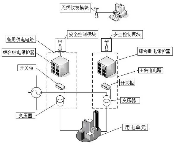
[0034] Such as figure 1 As shown, the present invention designs a self-organizing self-healing power distribution equipment, including a main power supply circuit, a backup power supply circuit and a monitoring terminal; A switch cabinet connected to the protector; also includes a wireless transceiver module connected to the monitoring terminal; The safety control module connected with the controller; the safety control module includes a control module and a wireless transceiver module; each of the safety control modules and the wireless transceiver module connected to the monitoring terminal communicate with each other through a wireless network.

[0035] A self-assembly and self-healing power distribution equipment designed by the present invention, in which the integrated relay protector, that is, the transformer pro...


PUM


Abstract

The invention relates to self-assembling and self-healing power distribution equipment, comprising a main power supply circuit, a secondary power supply circuit and a monitoring terminal. The main power supply circuit comprises a transformer, comprehensive relay protectors and a switch cabinet, wherein the switch cabinet is respectively connected with the transformer and the comprehensive relay protectors, and the main power supply circuit further comprises a wireless transmitting-receiving module connected with the monitoring terminal. The secondary power supply circuit and the main power supply circuit are the same in structure, and each one of the main power supply circuit and the secondary power supply circuit respectively comprises a safe control module connected with a corresponding comprehensive relay protector; each safe control module comprises a control module and a wireless transmitting-receiving module; and the safe control modules are communicated with the wireless transmitting-receiving modules connected with the monitoring terminal through a wireless network. The invention further relates to a safe switching method of the self-assembling and self-healing power distribution equipment, which can be used for monitoring a power utilization unit in real time. The safe switching method provided by the invention has a self-protection function, can realize automatic switching, and can prevent the transformer from various accidents which have chance to occur.

Description

technical field [0001] The invention relates to a self-assembling and self-healing power distribution equipment and a method for safe switching thereof. Background technique [0002] Smart power grids is the intelligence of the power grid, also known as "grid 2.0", which is based on an integrated, high-speed two-way communication network, through advanced sensing and measurement technology, advanced equipment Technology, advanced control methods and application of advanced decision support system technology to achieve the goals of reliability, security, economy, efficiency, environmental friendliness and safe use of the power grid. Provide power quality that meets the needs of users in the 21st century, allow access to various forms of power generation, activate the power market, and optimize and efficient operation of assets. [0003] Smart grid is the latest trend in the development and transformation of the world's power system, and it is an inevitable requirement for en...

Claims


Application Information

Patent Timeline
Patent Type & Authority Applications(China)
IPC IPC(8): H02J9/06H02J13/00
CPCY02B70/30Y02B90/20Y04S20/12Y04S20/20Y04S20/248Y04S40/126
Inventor 裴文江沈彦真王开蒋丹晴孙庆庆张毅峰叶晶晶吕婉缪瑞华杨洋
Owner SOUTHEAST UNIV
Why Eureka
Try Eureka