Wireless charging transmitting system

A transmission system and wireless charging technology, applied in electromagnetic wave systems, electrical components, circuit devices, etc., can solve problems such as loss, scrapped circuit boards, and damaged components

Inactive Publication Date: 2012-08-15
CHERY AUTOMOBILE CO LTD
View PDF5 Cites 3 Cited by
  • Summary
  • Abstract
  • Description
  • Claims
  • Application Information

AI Technical Summary

Problems solved by technology

[0003] In the existing wireless charging process, during the energy transmission process of the wireless transmission system, the transmission system always transmits.

Method used


Image

  • Wireless charging transmitting system
  • Wireless charging transmitting system
  • Wireless charging transmitting system

Examples


Embodiment Construction

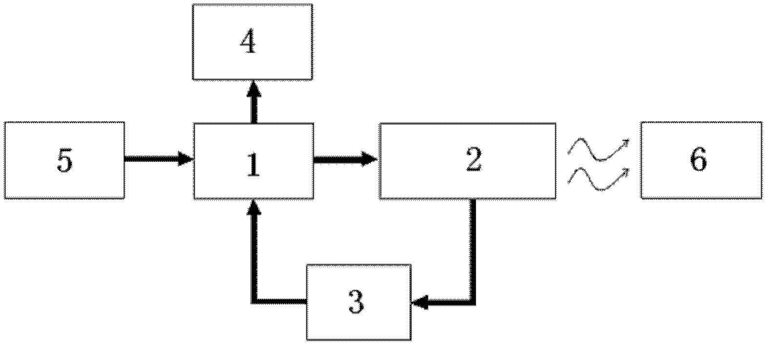
[0020] Such as figure 1 As shown, in the present invention, the central processing unit 1 controls the LLC electromagnetic resonance unit 2 and the indicating unit 4 respectively; the load detection unit 3 is connected to the central processing unit 1 and the LLC electromagnetic resonance unit 2 respectively; DC voltage, when the load detection unit 3 detects that the receiving system 6 is approaching, it transmits the feedback signal to the central processing unit 1 to control the LLC electromagnetic resonance unit 2, thereby realizing the automatic opening and closing of the transmitting system while ensuring the transmission efficiency.

[0021] So the present invention includes a central processing unit 1, a DC power supply unit 5 for providing power to the central processing unit 1, an LLC electromagnetic resonance unit 2 controlled by the central processing unit 1, a load detection unit 3 for detecting the load state, and a load detection unit for detecting Indication un...


PUM


Abstract

The invention discloses a wireless charging transmitting system which is characterized in that an LLC (Logic Link Control) electromagnetic resonance unit and an indicating unit are controlled respectively by a central processing unit; a load detection unit respectively accesses the central processing unit and the LLC electromagnetic resonance unit; and a direct current power supply unit provides direct current voltage for the central processing unit. Due to adoption of the circuit structure, the transmitting system has the following advantages that 1, the automatic powered-on and powered-off of the transmitting system is realized while ensuring the transmission efficiency of the whole transmitting system; 2, the fault rate of devices is reduced, production is lowered and costs are maintained; and 3, the structure is simple, and the system is suitable for transforming the existing products.

Description

technical field [0001] The invention relates to the field of wireless charging, in particular to a wireless charging transmitting system. Background technique [0002] Wireless charging is to charge electronic products through the principle of electromagnetic resonance. The whole wireless charging system consists of two parts, one is the transmitting system connected to the power supply, and the other is the receiving system on the electronic product. As long as it is within a certain range, the power supply can Instantaneously transmitted from the transmitting system to the corresponding receiving system. [0003] In the existing wireless charging process, during the energy transmission process of the wireless transmission system, the transmission system always transmits. Since it is always in the working state, the components are often damaged, and the entire circuit board is scrapped, resulting in unnecessary losses. [0004] How to reduce the damage rate of components w...

Claims


Application Information

Patent Timeline
IPC IPC(8): H02J17/00H02J50/10H02J50/80
Inventor 陈龙田照辉王晓辉
Owner CHERY AUTOMOBILE CO LTD
Why Eureka
Try Eureka