Flame hole unit structure of a gas burner

A technology of gas burners and flame holes, which is applied in the direction of gas fuel burners, burners, burners, etc., can solve the problems of increased manufacturing costs, incomplete combustion, and increased pressure loss, so as to reduce time and cost and prevent unsatisfactory Effect of complete combustion and reduced degree of deformation

Inactive Publication Date: 2012-08-15
KYUNGDONG NAVIEN
View PDF8 Cites 2 Cited by
  • Summary
  • Abstract
  • Description
  • Claims
  • Application Information

AI Technical Summary

Problems solved by technology

[0010] However, such a flame hole structure using a metal fiber mat or a ceramic plate requires a large amount of material cost, and the manufacturing cost is increased due to a troublesome manufacturing method, and the pressure loss is increased due to the complicated structure of the pre-mixer, so the flame is unstable. or noise problems
[0011] In addition, when the metal fiber mat produced by weaving is used as the flame hole material, the operator needs to pull the metal fiber mat to assemble the burner, so part or all of the metal fiber mat may be damaged. Incomplete combustion or backfire may occur due to non-uniform flame hole size, and the softness of the material properties of the metal fiber mat may cause uneven deformation of the combustion surface and flame hole due to sagging after installation.
[0012] In addition, when the ceramic plate produced by the above-mentioned sintering method is used as the material of the flame hole, if the condensed water generated in the heat exchanger falls on the combustion surface during upward combustion, the surface of the flame hole is damaged by water, Produces flame holes of non-uniform shape, which has the problem of the possibility of incomplete combustion

Method used


Image

  • Flame hole unit structure of a gas burner
  • Flame hole unit structure of a gas burner
  • Flame hole unit structure of a gas burner

Examples


Embodiment Construction

[0041] Hereinafter, the structures and functions of preferred embodiments of the present invention will be described in detail with reference to the accompanying drawings.

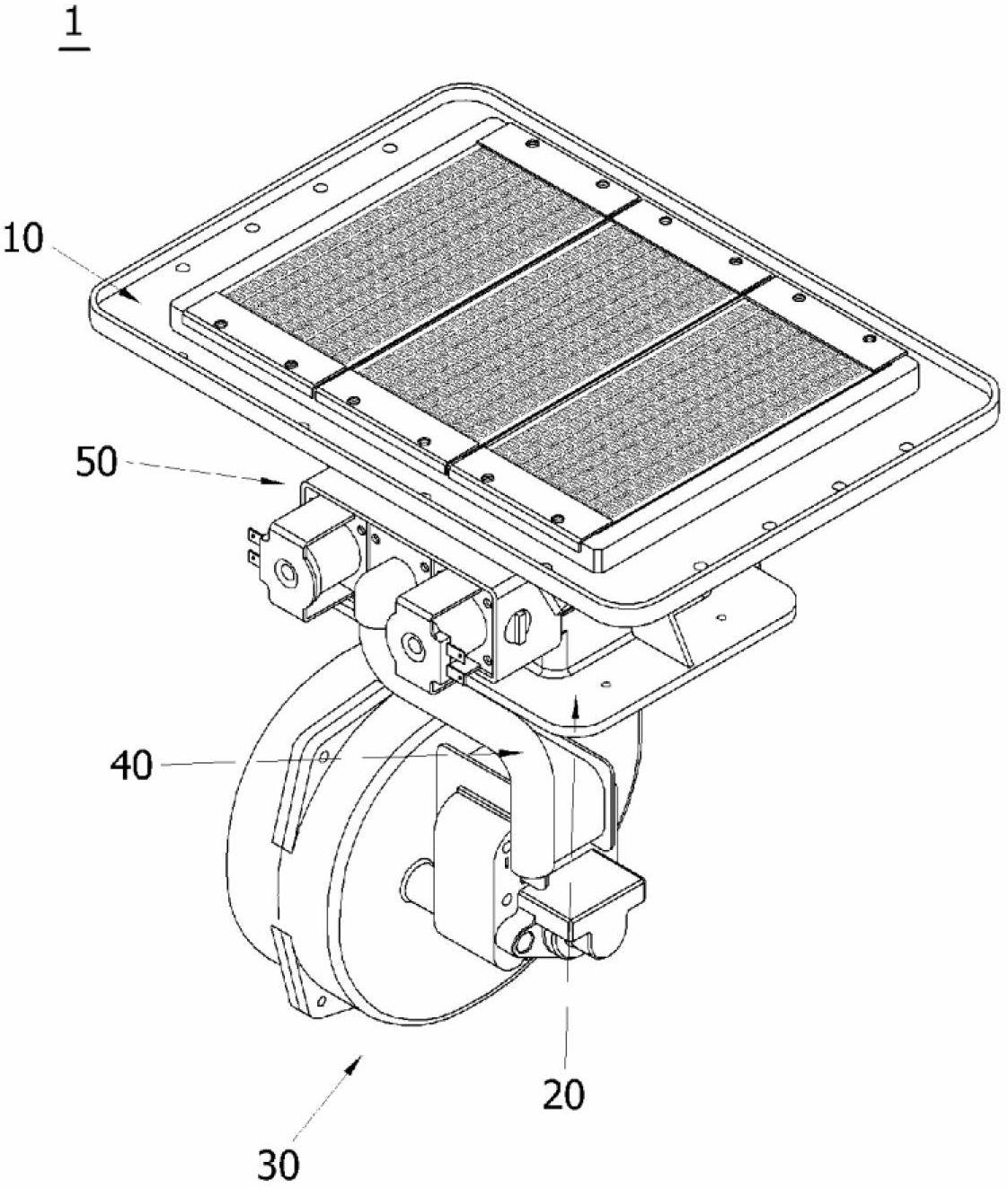
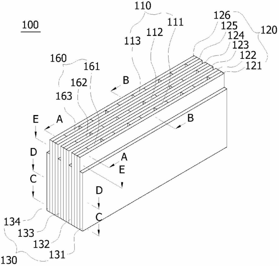
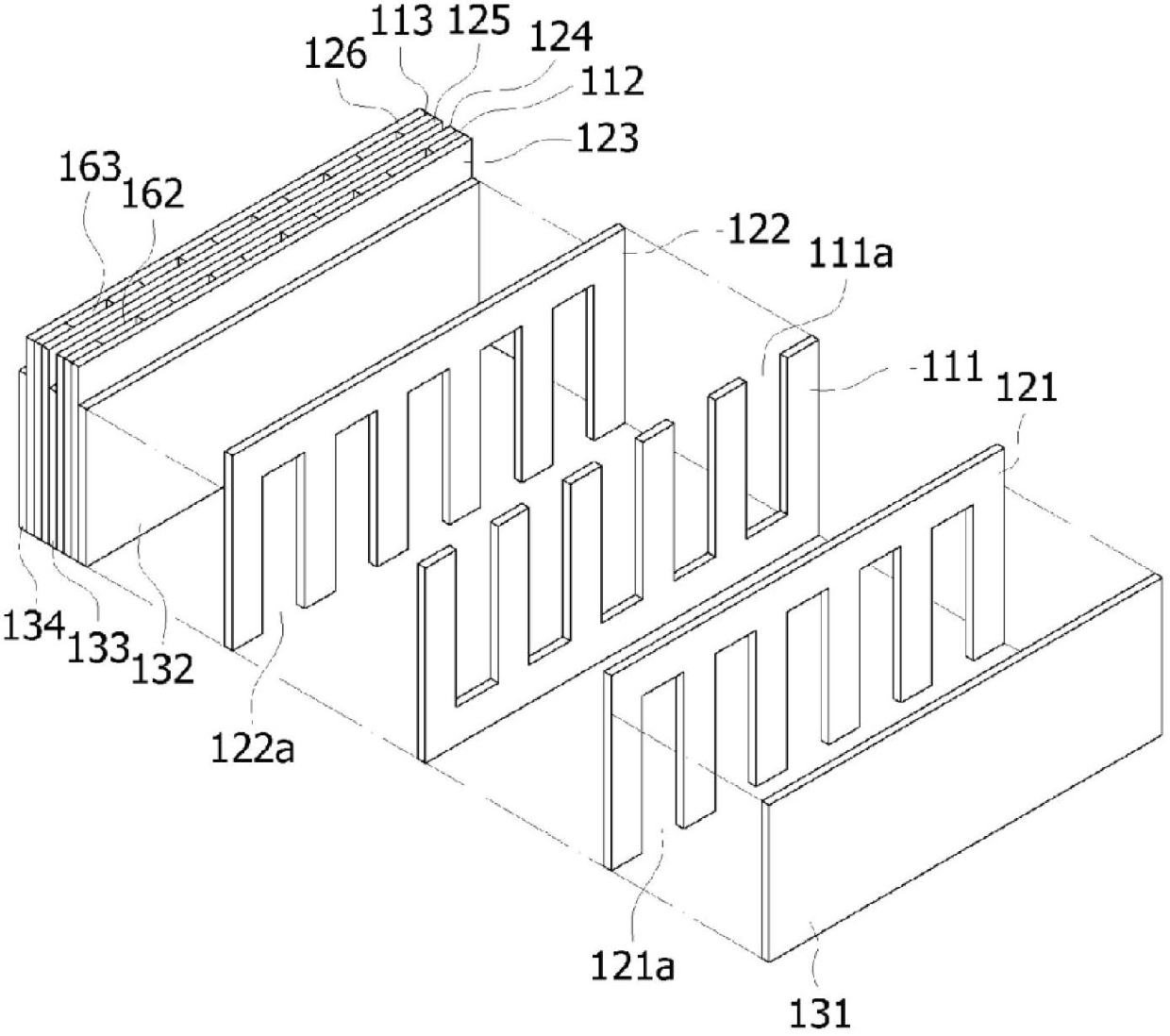
[0042] figure 2 It is a perspective view of the flame hole structure of the gas burner of the present invention, image 3 for figure 2 Partial exploded perspective view of , Figure 4 for figure 2 The A-A line datum cross-section diagram, Figure 5 for figure 2 The B-B line datum section diagram, Image 6 for figure 2 The C-C line datum section diagram, Figure 7 for figure 2 The D-D line datum section diagram, Figure 8 for figure 2 E-E line datum section diagram.

[0043] The flame hole portion 100 of the gas burner of the present invention is characterized in that it is composed of a structure in which a plurality of thin plates are stacked and assembled, and a passage for the mixed gas of gas and air to move is formed on the inside of the stacked plates, and the passage is dredged to ...


PUM


Abstract

The present invention relates to a flame hole unit structure of a gas burner for simplifying, easily assembling, and manufacturing a structure of a burner flame hole unit by overlapping a plurality of plates of which portions are cut so that the cut portions may be intersected with each other, and by forming flame holes and mixture channels of gas and air through a gap between the cut portions. To realize said purpose, the flame hole unit structure of the gas burner of the present invention has a plurality of flame holes in which a mixture of gas and air is sprayed to form a flame, and the plurality of plates of which the portions are cut are overlapped together, wherein the cut portions are intersected and overlapped with each other between the adjacent plates, thereby forming the flame holes and the mixture channels of gas and air through the gap between the cut portions.

Description

technical field [0001] The present invention relates to a flame hole structure of a gas burner, and more particularly relates to a flame hole structure of a gas burner as follows: by overlapping a plurality of cut plates, the cut parts of the plates cross each other, and by cutting The slits in the opened part form the gas-air mixed gas flow path and the flame hole, thereby simplifying the structure of the burner flame hole, and can be easily assembled and manufactured. Background technique [0002] Gas burners generally used in combustion equipment such as boilers or water heaters can be divided into Bunsen burners and pre-mixed burners according to the way of mixing gas and air for combustion. [0003] The Bunsen burner is a burner that supplies the minimum amount of primary air required for combustion at the nozzle where the gas is injected, and supplies excess secondary air to the part where the flame is formed to achieve complete combustion. It has the advantage of exce...

Claims


Application Information

Patent Timeline
Patent Type & Authority Applications(China)
IPC IPC(8): F23D14/02F23D14/58
CPCF23D14/586F23D2213/00F23D14/02F23D14/58
Inventor 闵泰植
Owner KYUNGDONG NAVIEN
Why Eureka
Try Eureka