

Novel horizontal lathe chuck mechanism
A horizontal lathe and lathe technology, applied in turning equipment, turning equipment, metal processing equipment, etc., can solve the problems of easy deformation and damage of the chuck, poor versatility, high failure rate, etc., and achieve not easy deformation and damage, simple structure and low failure rate low effect
Inactive Publication Date: 2012-08-22
李勇
View PDF0 Cites 0 Cited by
- Summary
- Abstract
- Description
- Claims
- Application Information
AI Technical Summary
Problems solved by technology
[0003] The object of the present invention is to provide a new type of chuck mechanism for horizontal lathes, which overcomes the defects of existing chuck mechanisms such as complex structure, high failure rate, easy deformation and damage of the chuck, and poor versatility
Method used
View moreImage
Smart ImageViewing Examples

Examples
Embodiment Construction
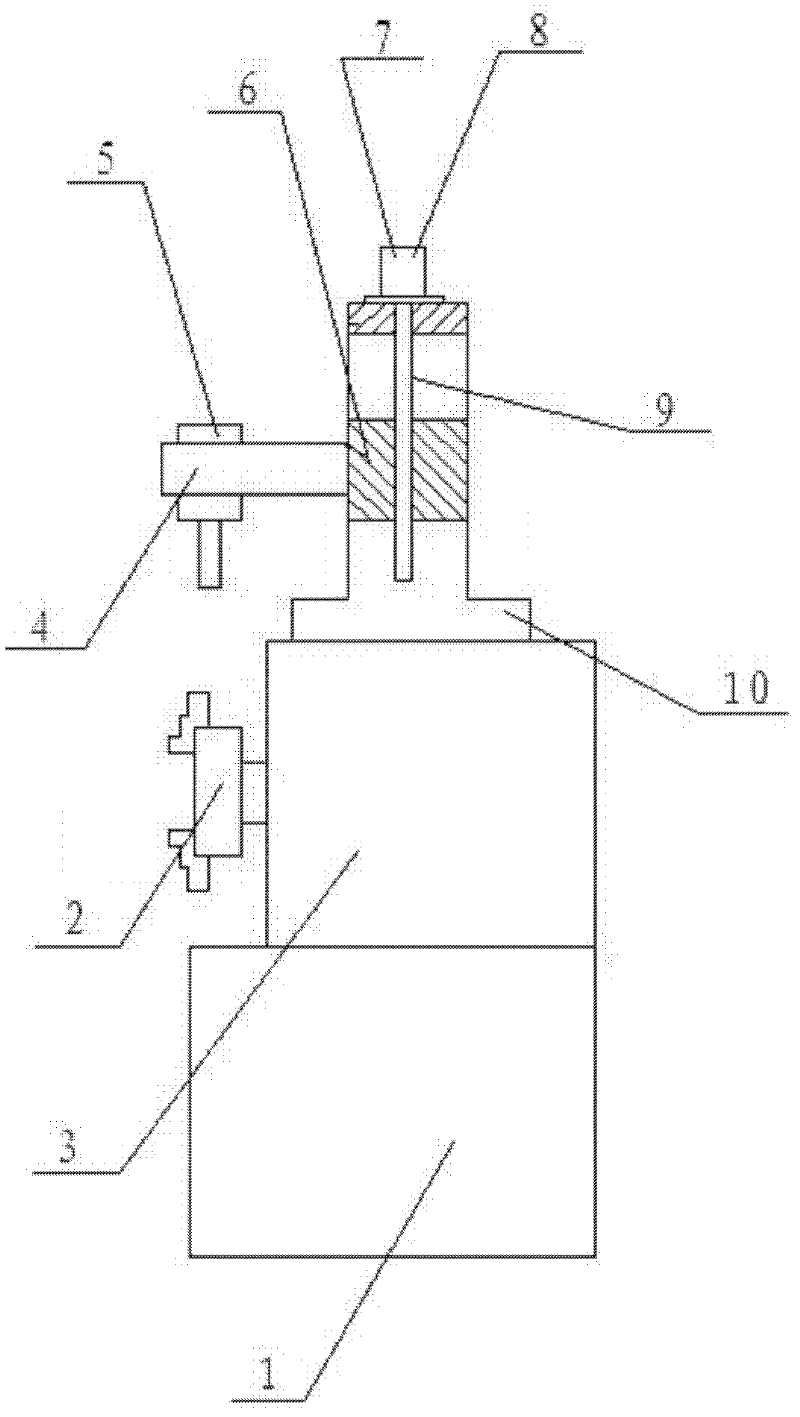
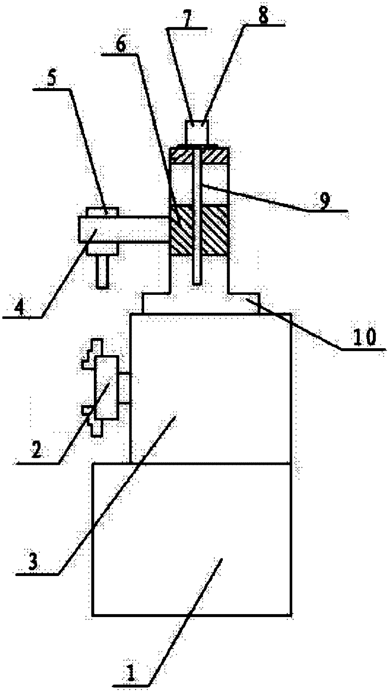
[0009] The chuck mechanism of the horizontal lathe is a horizontal lathe composed of a horizontal lathe body (1), a multipurpose chuck (2), a lathe box (3), and a lathe cantilever (4). The column (7) is installed on the lathe box (3 ), install the slider (6) in the middle of the column (7), connect the lathe cantilever (4) with the slider (6), and install the pneumatic mechanism (8) on the lathe cantilever ( 4), install the steam motor mechanism (10) on the top end of the column (7), and put one end of the lathe screw (9) through the slider (6) to the output shaft of the steam motor mechanism (10) Connect, and the other end is connected with the slider (6) through threaded fit.
Login to View More PUM
 Abstract
The invention relates to a novel horizontal lathe chuck mechanism which is provided with a horizontal lathe composed of a horizontal lathe body, a multipurpose chuck, a lathe box and a lathe cantilever; a vertical column is mounted on the lathe box; a slide block is mounted on the middle part of the vertical column; the lathe cantilever is connected with the slide block; a pneumatic mechanism is mounted on the lathe cantilever through an automatic butt joint port; a steam-driven motor mechanism is mounted at the top of the vertical column; one end of a lathe screw rod is in butt joint with an output shaft of the steam-driven motor mechanism through the slide block; and the other end of the lathe screw rod is connected with the slide block in a thread fit form.
Description
technical field [0001] The invention relates to a chuck mechanism, in particular to a novel horizontal lathe chuck mechanism, which belongs to the technical field of horizontal lathe cutting. Background technique [0002] The chuck mechanism is a component of the horizontal lathe. The function of the chuck on the horizontal lathe is to clamp or loosen the workpiece. Generally, it is done manually. In order to improve the production efficiency of the horizontal lathe, in some The horizontal machine tool is designed as a chuck lathe with a motorized function structure. This kind of horizontal chuck lathe improves the work efficiency in a certain procedure. However, due to the complex structure, high failure rate, and easy deformation and damage of the chuck , the defect of poor versatility, so it brings a lot of corresponding difficulties to use. Contents of the invention [0003] The object of the present invention is to provide a novel chuck mechanism for a horizontal lat...
Claims
Login to View More Application Information
Patent Timeline
 Patent Type & AuthorityApplications(China)
IPC IPC(8): B23B3/06
Inventor李勇
Owner李勇