Pole piece feeding device

A pole piece and piece feeding technology, which is applied in the field of pole piece feeding device, can solve the problems of over-tolerance, offset, and large size error of the pole piece, etc., to overcome deformation and wrinkling, improve process quality, The effect of reducing size error

Active Publication Date: 2012-08-22
GEESUN AUTOMATION TECH
View PDF5 Cites 20 Cited by
  • Summary
  • Abstract
  • Description
  • Claims
  • Application Information

AI Technical Summary

Problems solved by technology

[0002] The pole pieces used for lithium-ion power batteries are usually made of thinner aluminum or copper foils. During the process of sending them to the laser cutting station for pole piece cutting, due to the thinness of the pole pieces, it is easy to deform and crack. Wrinkles and other problems, resulting in the scrapping of the pole piece after cutting because the flatness does not meet the requirements
[0003] In the prior art, sheet feeding methods such as double-roller type, rear clip type, or upper and lower belt pinch feeding are generally used to convey the sheet material. Although the problem of deformation and wrinkling of the pole piece can be solved to a certain extent, for thinner copper foil or The effect of aluminum foil is poor, and it is still easy to damage the pole piece; in addition, it is difficult to accurately control the length and position of the pole piece in these feeding methods, and it is easy to cause the phenomenon of out-of-tolerance or offset of the fixed length, so it is inevitable to use The size error of the pole piece cut out by laser is relatively large, and the battery manufacturing process has strict requirements on the dimensional consistency between the pole piece and the battery cell, and the pole piece with large size deviation obviously cannot meet this requirement

Method used


Image

  • Pole piece feeding device
  • Pole piece feeding device
  • Pole piece feeding device

Examples


Embodiment Construction

[0026] The present invention will be further described in detail below through specific embodiments in conjunction with the accompanying drawings.

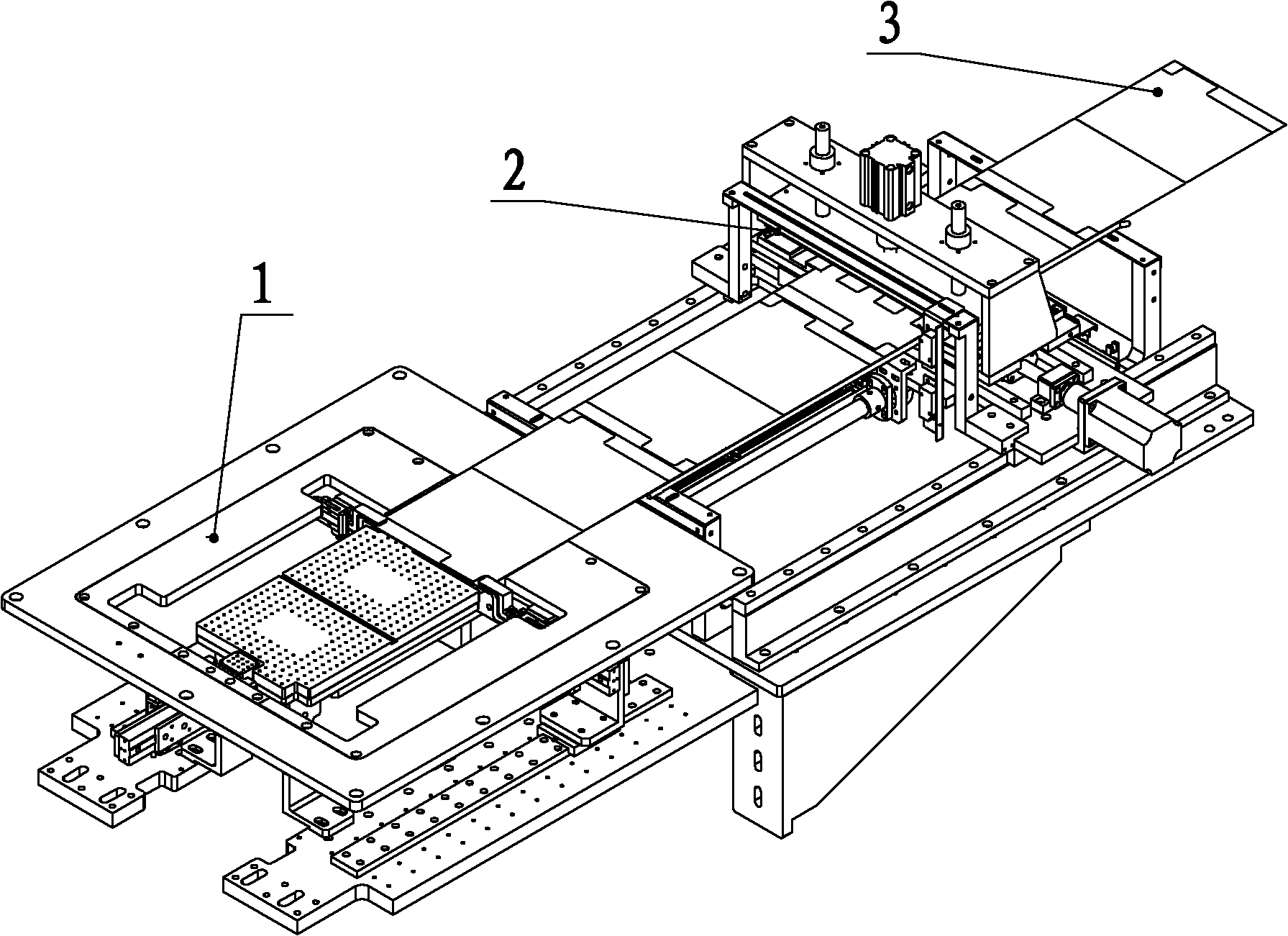
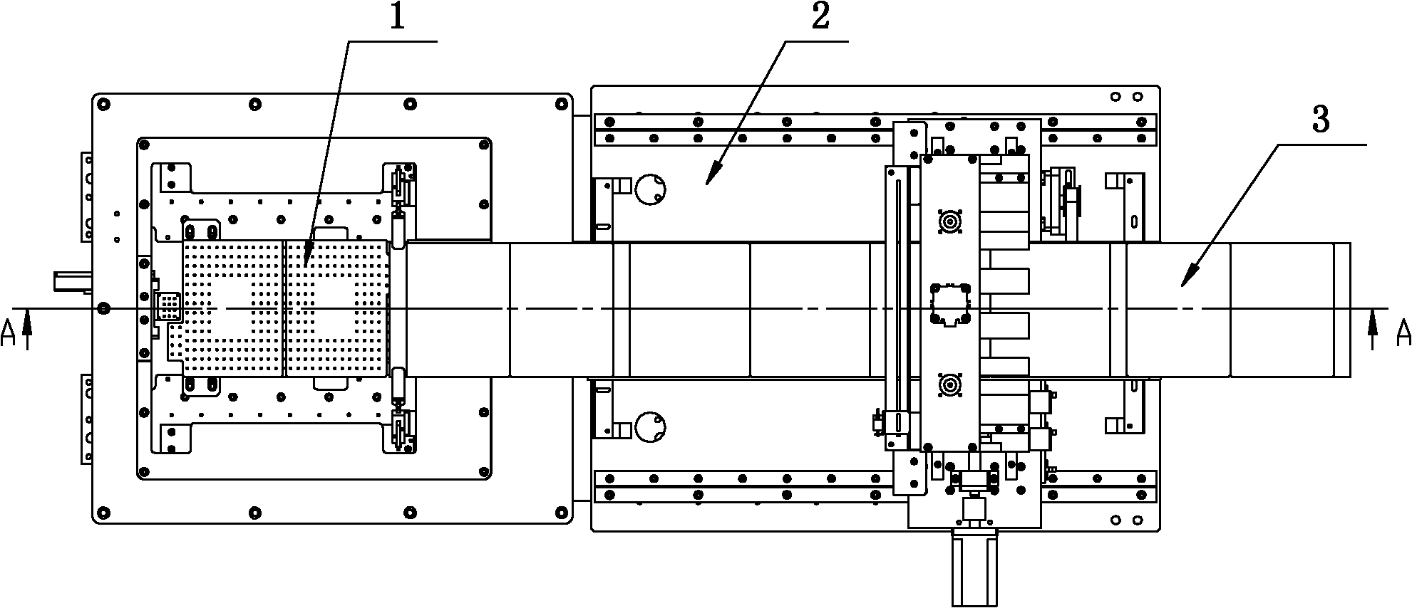
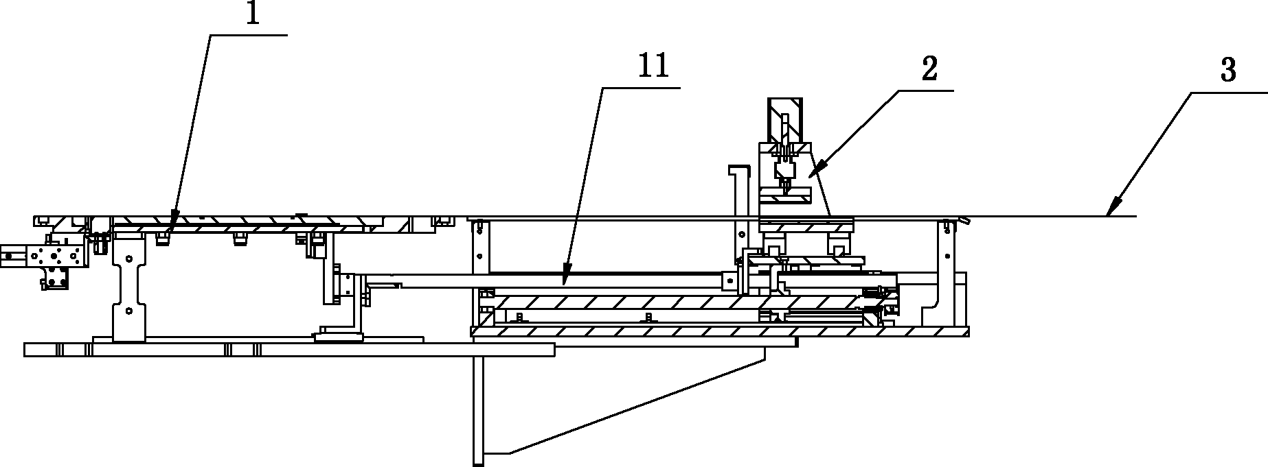
[0027] Please refer to figure 1 , A pole piece feeding device in this embodiment mainly includes a clamping manipulator part 1 and a length-feeding part 2, both of which are fixed on the same base. like Figure 2 to Figure 5 As shown, the gripping manipulator part 1 mainly includes a base frame 4, a push rod 11, a first gripping mechanism and a suction mechanism; the fixed-length part 2 mainly includes a second gripping mechanism, a deviation correction mechanism, a supporting sheet mechanism and a driving first gripping mechanism. 2. The feeding mechanism that moves back and forth between the clamping mechanism. The first clamping mechanism is installed on the front end of the push rod 11, and the second clamping mechanism is installed on the rear end of the push rod 11. When the pole piece 3 starts to feed, the material rolle...


PUM


Abstract

The invention discloses a pole piece feeding device. The device comprises a material clamping manipulator part and a feeding fixed-length part, wherein the material clamping manipulator part comprises push rods and a first material clamping mechanism for clamping the front part of a pole piece; the feeding fixed-length part comprises a second material clamping mechanism for clamping the middle part of the pole piece and a feeding mechanism for driving the second material clamping mechanism to move back and forth; the first material clamping mechanism is installed at the front ends of the push rods; and the second material clamping mechanism is installed at the rear ends of the push rods. The device can be widely used for conveying and cutting such pole pieces as battery pole pieces and super capacitor pole pieces, can solve the problem that the pole pieces are easy to deform and wrinkle in the conveying process in the prior art, simultaneously avoids feeding fixed-length out of tolerance and left and right offset through fixed-length feeding and rectification control, reduces the size error of the pole piece and obviously improves the quality of the pole piece feeding process.

Description

technical field [0001] The invention relates to the field of batteries, in particular to a pole piece feeding device for delivering lithium ion battery or supercapacitor pole pieces. Background technique [0002] The pole pieces used for lithium-ion power batteries are usually made of thinner aluminum or copper foils. During the process of sending them to the laser cutting station for pole piece cutting, due to the thinness of the pole pieces, it is easy to deform and crack. Wrinkles and other problems, resulting in the flatness of the pole piece after cutting does not meet the requirements and scrapped. [0003] In the prior art, sheet feeding methods such as double-roller type, rear clip type, or upper and lower belt pinch feeding are generally used to convey the sheet material. Although the problem of deformation and wrinkling of the pole piece can be solved to a certain extent, for thinner copper foil or The effect of aluminum foil is poor, and it is still easy to damag...

Claims


Application Information

Patent Timeline
IPC IPC(8): B23Q7/18
Inventor 陈强徐国根毛羽
Owner GEESUN AUTOMATION TECH
Why Eureka
Try Eureka