High-strength reinforcing steel bar with spiral fins and processing method of high-strength reinforcing steel bar

A processing method and technology of ribbed steel bars, which are applied in the field of high-strength spiral rib steel bars and their processing, can solve the problems of poor ductility of spiral rib steel wires, inability to connect spiral rib steel wires with threads, and a narrow range of use, and achieve high anchoring strength and rigidity. Anchorage performance, good for anti-seismic effect

Active Publication Date: 2012-08-22
TIANSHUN GROUP +2
View PDF3 Cites 18 Cited by
  • Summary
  • Abstract
  • Description
  • Claims
  • Application Information

AI Technical Summary

Problems solved by technology

[0006] In addition, the existing process and the spiral-rib steel wire produced by it have the following disadvantages: due to the first drawing to increase the strength, and then the quenching and tempering treatment, the ductility of the spiral-rib steel wire is poor and the strength-to-yield ratio is low; The strength is increased by drawing, resulting in a low yield; the molds are often changed, resulting in high production costs; the size is too small, resulting in a narrow range of use; a large amount of waste acid produced in the pickling and phosphating process cannot

Method used


Image

  • High-strength reinforcing steel bar with spiral fins and processing method of high-strength reinforcing steel bar
  • High-strength reinforcing steel bar with spiral fins and processing method of high-strength reinforcing steel bar
  • High-strength reinforcing steel bar with spiral fins and processing method of high-strength reinforcing steel bar

Examples


Embodiment 1

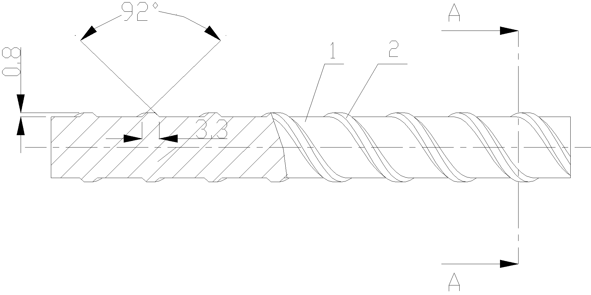
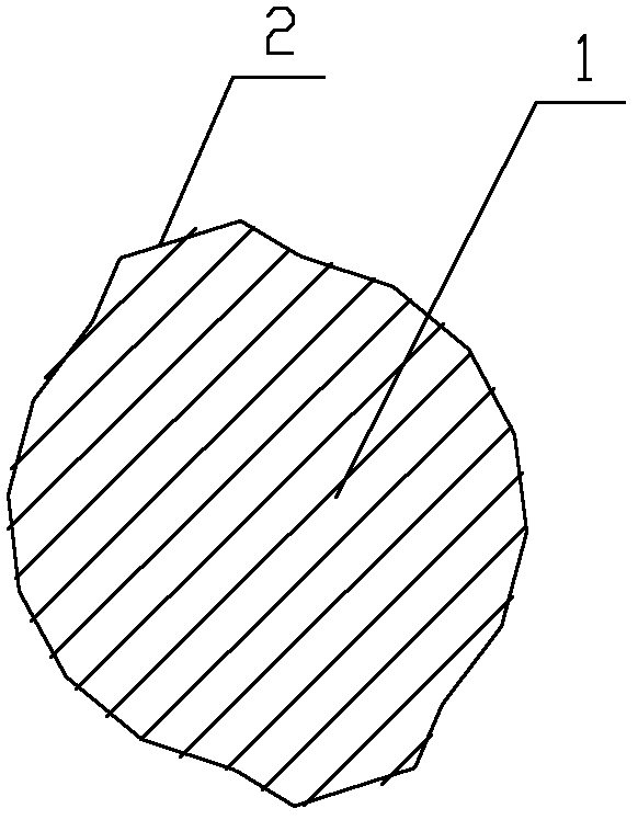
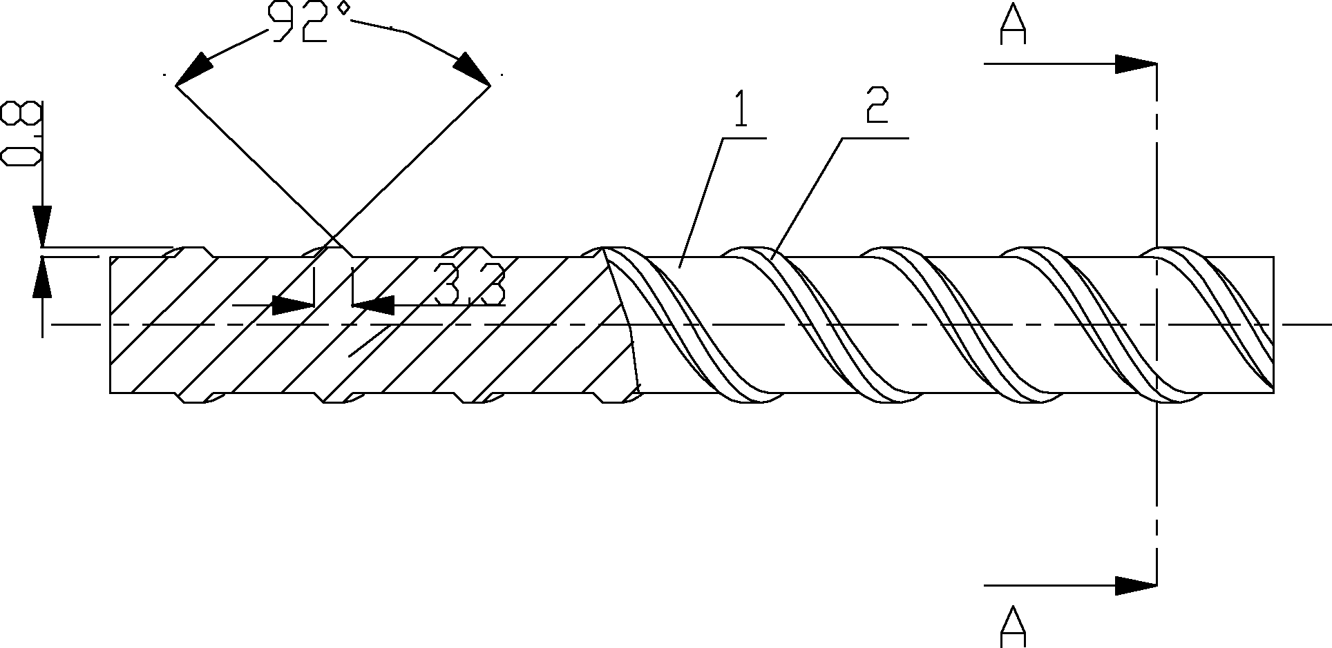
[0030] This embodiment proposes a high-strength spiral rib steel bar, the structure shown in 1, including a steel bar body 1 and two spiral ribs 2 on the surface of the steel bar body, the spiral ribs 2 are continuously distributed on the surface of the steel bar body, and each continuous spiral rib 2 The angle between the two tangent lines between the two sides and the surface of the steel bar is 90°, and the width of each continuous spiral rib is 3mm and the height is 0.5mm.

[0031] The high-strength spiral rib steel bar of this embodiment contains the following components by weight percentage: C: 0.25%, Si: 0.1%, Mn: 0.3%, Nb: 0.04%, Cr: 0.08%, V: 0.01%, B: 0.002 %, Mo: 0.001%, Al: 0.015%, S: 0.002%, Ti: 0.008%, Ni: 0.004%, compound rare earth: 3%, and the balance is Fe. In the composite rare earth, the following components are contained by weight percentage: La: 25%, Ce: 20%, Y: 8%, Sc: 12%, Gd: 5%, Sm: 5%, Dy: 5%, Pr: 20 %.

[0032] The processing method of high-streng...

Embodiment 2

[0037] This embodiment proposes a high-strength spiral rib steel bar, the structure shown in 1, including a steel bar body 1 and two spiral ribs 2 on the surface of the steel bar body, the spiral ribs 2 are continuously distributed on the surface of the steel bar body, and each continuous spiral rib 2 The angle formed by the two tangent lines between the two sides and the reinforcement surface is 92°, and the width of each continuous spiral rib is 3.3mm and the height is 0.7mm.

[0038] The high-strength spiral rib steel bar of this embodiment contains the following components by weight percentage: C: 0.3%, Si: 0.15%, Mn: 0.4%, Nb: 0.045%, Cr: 0.085%, V: 0.03%, B: 0.0025 %, Mo: 0.002%, Al: 0.025%, S: 0.0025%, Ti: 0.0085%, Ni: 0.0045%, compound rare earth: 4%, and the balance is Fe. In the composite rare earth, the following components are contained by weight percentage: La: 33%, Ce: 17%, Y: 5%, Sc: 10%, Gd: 5%, Sm: 7%, Dy: 3%, Pr: 20 %.

[0039] The processing method of high...

Embodiment 3

[0044] This embodiment proposes a high-strength spiral rib steel bar, the structure shown in 1, including a steel bar body 1 and two spiral ribs 2 on the surface of the steel bar body, the spiral ribs 2 are continuously distributed on the surface of the steel bar body, and each continuous spiral rib 2 The angle between the two tangent lines between the two sides and the steel bar surface is 95°, and the width of each continuous spiral rib is 3.5mm and the height is 0.9mm.

[0045] The high-strength spiral rib steel bar of this embodiment contains the following components by weight percentage: C: 0.4%, Si: 0.2%, Mn: 0.45%, Nb: 0.05%, Cr: 0.09%, V: 0.04%, B: 0.003 %, Mo: 0.003%, Al: 0.03%, S: 0.003%, Ti: 0.009%, Ni: 0.005%, compound rare earth: 5%, and the balance is Fe. In the composite rare earth, the following components are contained by weight percentage: La: 35%, Ce: 15%, Y: 7%, Sc: 11%, Gd: 4%, Sm: 6%, Dy: 4%, Pr: 18 %.

[0046] The processing method of high-strength spi...


PUM


Abstract

The invention relates to a reinforcing steel bar and a processing method thereof, in particular to a high-strength reinforcing steel bar with spiral fins and a processing method of the high-strength reinforcing steel bar. The high-strength reinforcing steel bar consists of following components including, in weight percentage, from 0.25 to 0.4% of C, from 0.1 to 0.2% of Si, from 0.3 to 0.45% of Mn, from 0.04 to 0.05% of Nb, from 0.08 to 0.09% of Cr, from 0.01 to 0.04% of V, from 0.002 to 0.003% of B, from 0.001 to 0.003% of Mo, from 0.015 to 0.03 of Al, from 0.002 to 0.003% of S, from 0.008 to0.009% of Ti, from 0.004 to 0.005% of Ni, from 3 to 5% of composite rear earth and the balance Fe. The processing method includes using a roll to roll a reinforcing steel bar into a reinforcing steelbar with the continuous spiral fins on the surface in a hot state; feeding the reinforcing steel bar with the continuous spiral fins on the surface after hot rolling into a heating furnace and heating the reinforcing steel bar to the temperature of 880-990 DEG C; then fast cooling the reinforcing steel bar to the temperature of 650-680 DEG C by an online cooling device via compressed air or vaporous quenching liquid; quenching in a quenching device by water or quenching liquid for 15-25 seconds; and tempering after heating the reinforcing steel bar to the temperature of 500-550 DEG C via a tempering heating furnace. The high-strength reinforcing steel bar with the spiral fins has a good anchoring property, fine ductility and a high yielding-to-tensile ratio.

Description

Technical field [0001] The invention involves a steel bar and its processing method. Specifically, it is a high -strength spiral rib steel and its processing method. Background technique [0002] The currently used steel bars are threads, which are specific on the outer surface with crescent rib threads, threads are longitudinal convex tendons, cross -rib bite teeth, and are not continuous.The size of this thread is formulated in accordance with the standards of Soviet -building steel in the 1950s and 1960s. The diameter of the steel bar is between 6 and 50mm. It is widely used in the construction field and has been used to this day.Because the base of the thread size is 0.94, the effective area should be lost by about 6%to 11%due to the force of the horizontal ribs.Due to the surface of the reinforcement with longitudinal convex tendons, the adhesion and grip of the concrete in the reinforced concrete engineering are weak, and the reinforced concrete is in a state of force. Due ...

Claims


Application Information

Patent Timeline
IPC IPC(8): C22C38/54C21D8/00
Inventor 姚圣法吴海洋
Owner TIANSHUN GROUP
Why Eureka
Try Eureka