Hydroelectric generator

A technology for hydroelectric generators and water passages, applied in hydroelectric power generation, engine components, machines/engines, etc., can solve problems such as inconvenient installation and transportation, unfavorable separation of water and electricity, and large volume of the whole machine, so as to improve space utilization , compact structure, smooth and stable waterway

Inactive Publication Date: 2012-08-22
XIAMEN SOLEX HIGH TECH IND CO LTD +1
View PDF6 Cites 1 Cited by
  • Summary
  • Abstract
  • Description
  • Claims
  • Application Information

AI Technical Summary

Problems solved by technology

However, in the prior art, it is necessary to reserve a certain space in the hydroelectric generator as a water flow channel, so it has the following disadvantages: 1. The structure is relatively complicated and the cost is high; 2. It is not conducive to the separation of water and electricity; 3. The volume of the whole machine is relatively small. Big, inconvenient to install and transport

Method used


Image

  • Hydroelectric generator
  • Hydroelectric generator
  • Hydroelectric generator

Examples


Embodiment Construction

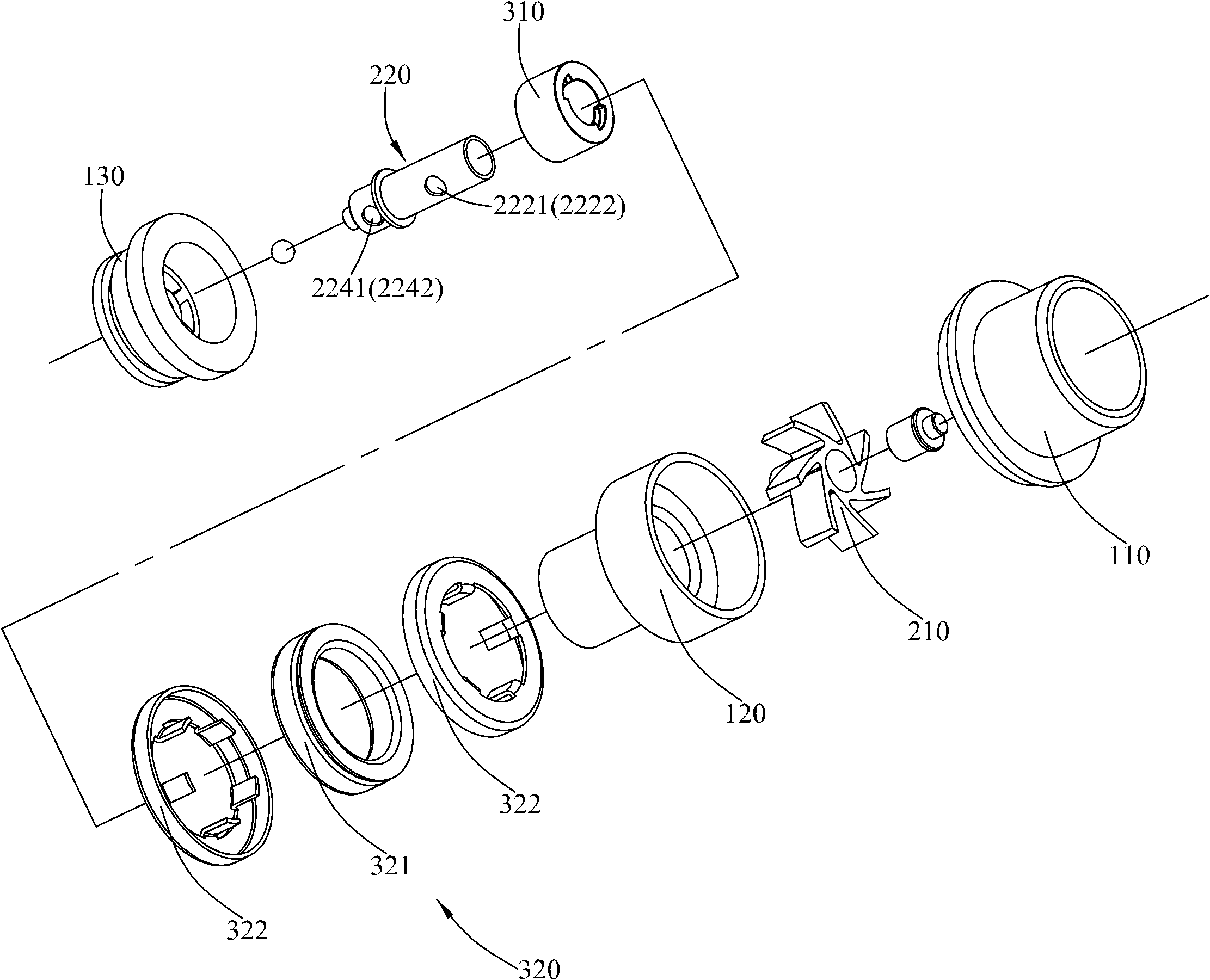
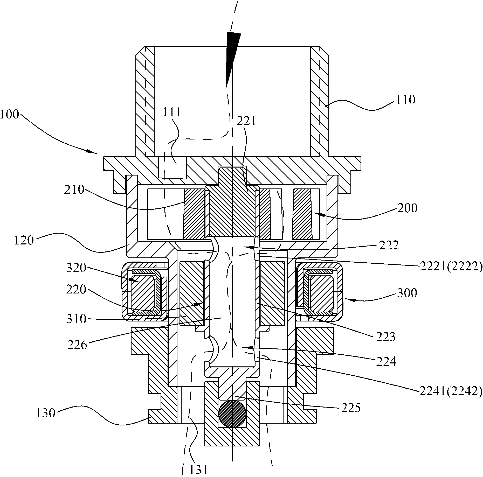
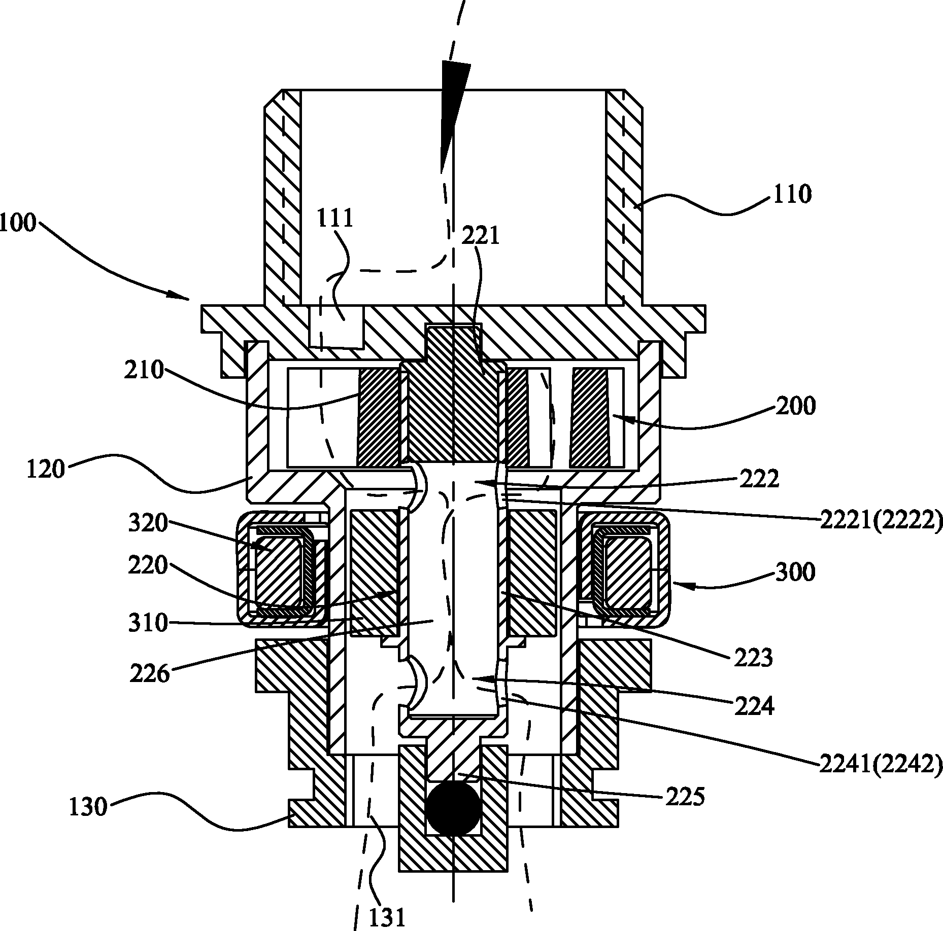
[0026] see figure 1 with figure 2 , is the hydraulic generator provided by the preferred embodiment of the present invention.

[0027] The hydroelectric generator includes a housing 100, a drive unit 200 and a power generation unit 300, wherein:

[0028] The casing 100 includes a plug 110, a casing 120 and a base 130, the plug 110 is provided with an inclined water hole 111, the drive unit 200 and the power generation unit 300 are arranged at the casing, and the base 130 is provided with at least one through hole 131 extending up and down.

[0029] The drive unit 200 includes an impeller 210 and a rotating shaft 220, the impeller 210 is arranged under the head section 221 of the rotating shaft and the plug 110, and communicates with the water source through the inclined water hole 111 of the plug 110; The rotating shaft 220 is divided into a head section 221, a first hole section 222, a fixed section 223, a second hole section 224 and a tail section 225, wherein the end of...


PUM


Abstract

The invention discloses a hydroelectric generator which comprises a shell, a driving unit and a generating unit. The driving unit can be rotationally arranged in the shell and comprises an impeller and a rotating shaft; the rotating shaft is provided with a head section, a fixed connecting section and a first opening section arranged between the head section and the fixed connecting section; the impeller is fixedly arranged on the head section of the rotating shaft; a water passing passage is arranged in the fixed connecting section; the water passing passage is provided with at least one water inlet hole which runs through the inside and outside of the water passing passage and is positioned at the position of the first opening section; the generating unit comprises a magnet and a coil assembly; the magnet is fixedly arranged outside the fixed connecting section; the coil assembly is fixedly arranged on the shell; and the axial positions of the magnet and the coil assembly are in fit. The hydroelectric generator has a compact and small structure, occupies a small space, is reasonable in production cost and is convenient to install and transport.

Description

technical field [0001] The invention relates to a hydraulic generator applied in the field of bathroom. Background technique [0002] In recent years, hydropower technology has been applied to the field of sanitary ware, such as hydropower showers or hydropower faucets with functions such as light emission, sound generation, and liquid crystal display temperature. Generally speaking, its hydroelectric power generation device mainly includes an impeller installed in a flow channel of a water pipe, a magnet rotor, and a stator with winding coils. The impeller rotates under the drive of the water flow, and drives the magnet rotor to rotate together. The magnet rotor rotates relative to the stator, causing changes in magnetic flux, generating induced electromotive force in the coil, thereby generating electric energy. [0003] This kind of hydroelectric generator converts the kinetic energy of tap water into electric energy, and is widely used in households, gardens, outdoors ...

Claims


Application Information

Patent Timeline
Patent Type & Authority Applications(China)
IPC IPC(8): F03B13/00F03B3/00F03B3/12F03B11/02
CPCY02E10/20
Inventor 马红亮陈健民金忠成周华松
Owner XIAMEN SOLEX HIGH TECH IND CO LTD
Why Eureka
Try Eureka