Full-automatic energy-saving clutch for vehicle
A fully automatic, clutch technology, applied in magnetic drive clutches, clutches, non-mechanical drive clutches, etc., can solve the problems of increasing the driver's driving action, wasting energy and unwilling to use it, and causing danger, reducing the number of starts and time. , the effect of reducing calorific value and saving fuel
- Summary
- Abstract
- Description
- Claims
- Application Information
AI Technical Summary
Problems solved by technology
Method used
Image
Examples
Embodiment 1
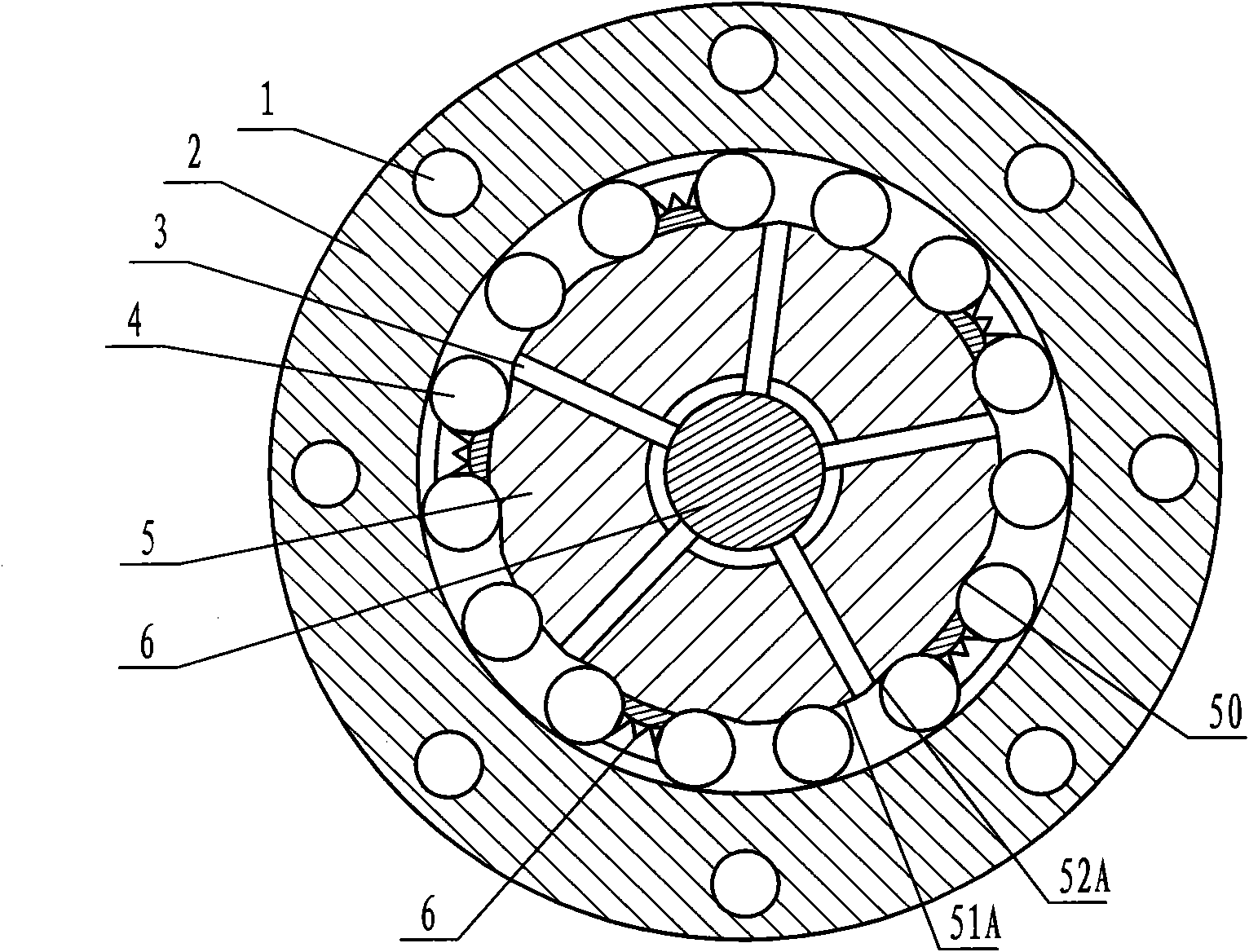
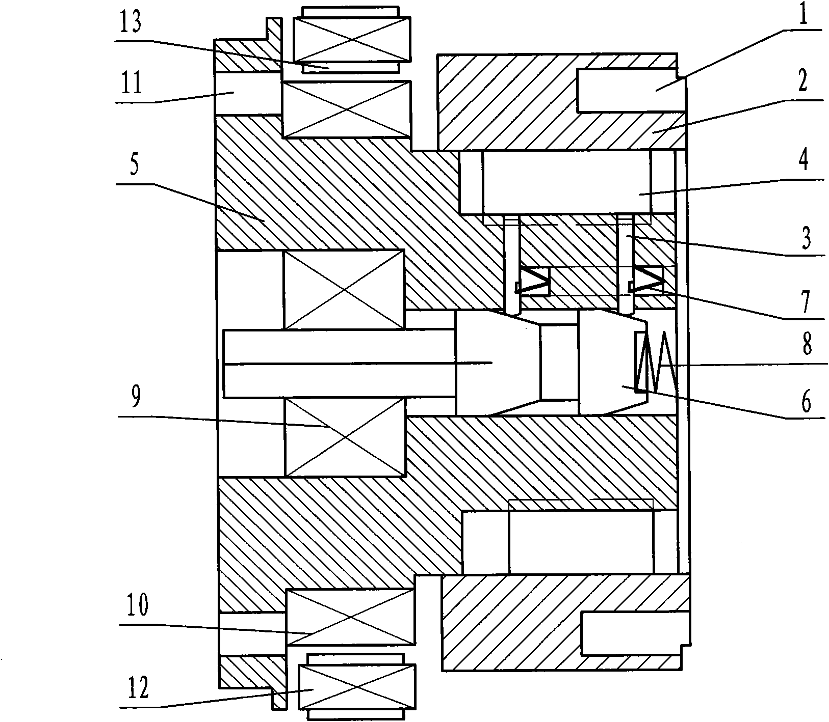
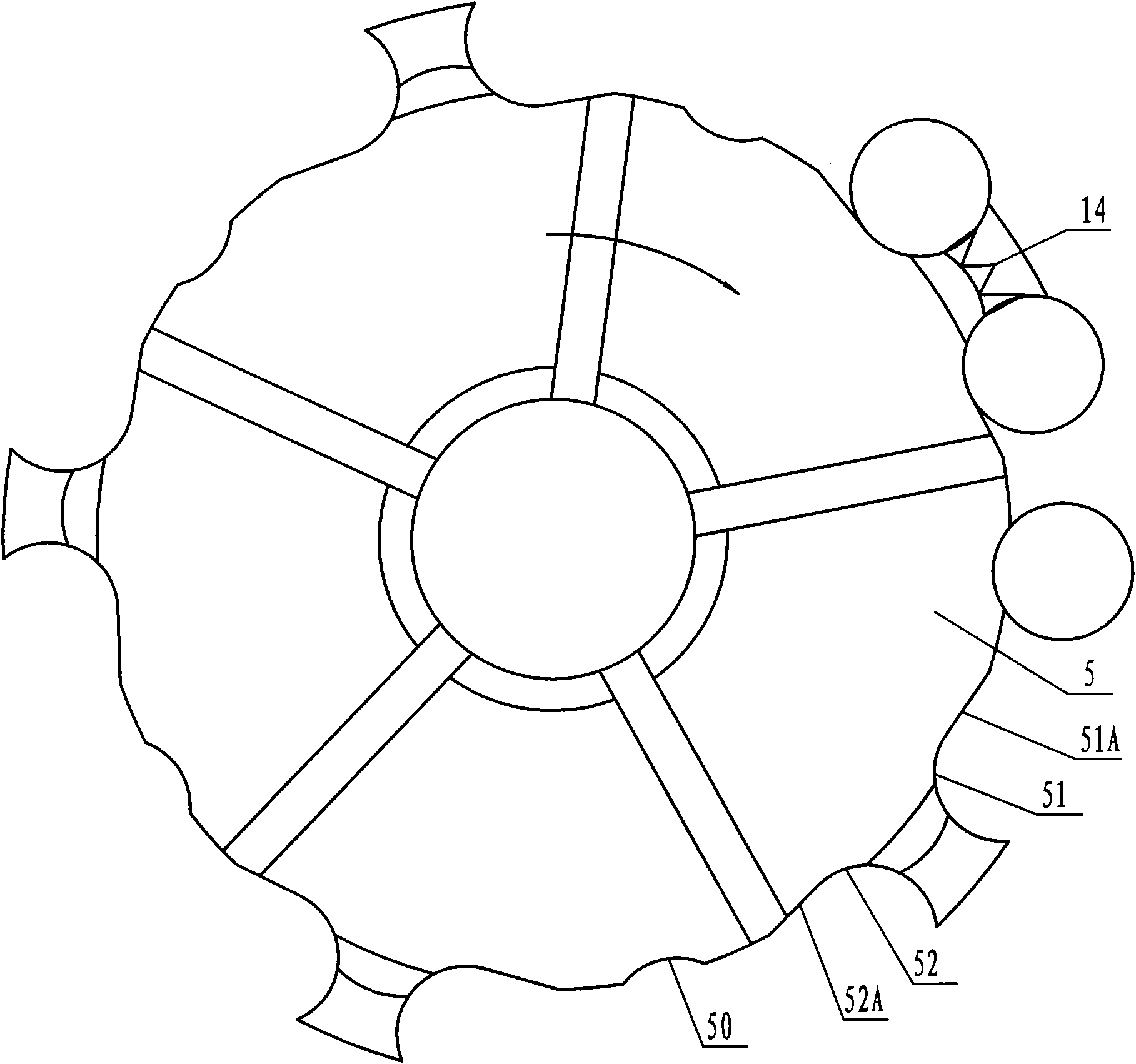
[0029] The main body of the fully automatic energy-saving clutch for vehicles in this embodiment includes an outer cover 2 and an inner shaft 5, a roller 4 arranged between the outer cover 2 and the inner shaft 5, a clutch pin 3 for controlling the movement of the roller 4, and a pin for controlling the action of the clutch pin 3. A generator composed of push rod 6, electromagnetic coil I for controlling the action of push rod 6, electromagnetic coil II for generating electricity and excitation coil 12. The inner shaft 5 is connected with the power output shaft of the gearbox through the inner shaft connecting hole 11, and the outer cover 2 is connected with the wheel transmission mechanism, that is, the wheel shaft, through the outer cover connecting hole 1. The structure diagram of this embodiment is as figure 1 and figure 2 shown. The jacket 2 is set on the outside of the inner shaft 5, the inner hole of the jacket is a cylindrical light hole, the outer surface of the in...
Embodiment 2
[0034] The difference between this embodiment and Embodiment 1 is that the shapes of the 15 grooves for storing the rollers are the same, and the shape is no longer set to be consistent with the outer circle shape of the roller 4, and the cross-sectional shape is a regular arc shape. Groove I. There are slopes on both sides of each groove, the slope in the direction opposite to the steering of the gearbox output shaft when the vehicle is moving forward is a forward slope, and the slope in the direction consistent with the steering of the gearbox output shaft when the vehicle is moving forward is a reverse slope The slope is also provided with clutch pins at the reverse slope, and other structures are the same as in Embodiment 1.
Embodiment 3
[0036] The difference between this embodiment and Embodiment 1 is that the electromagnetic coil II and the exciting coil are not installed outside the electromagnetic coil I, but a conductive ring is installed on the outer surface of the inner shaft, the conductive ring is connected with the electromagnetic coil I, and the conductive ring is connected with the inner shaft Insulation, the conductive ring is frictionally connected to the brush, the brush is electrically connected to the brake electric control mechanism, the reverse electric control mechanism, the slope and inertia sensor control mechanism, the engine state sensor control mechanism, and the wet road surface detection control mechanism, and the circuit is also connected in series Connected with a manual switch set in the cab. Like this, the on-off state of electromagnetic coil 1 is controlled by the reverse gear of brake pedal, reversing, also can be controlled by gradient and inertial control mechanism, slippery r...
PUM
 Abstract
Description
Claims
Application Information
 - R&D
- Intellectual Property
- Life Sciences
- Materials
- Tech Scout
- Unparalleled Data Quality
- Higher Quality Content
- 60% Fewer Hallucinations
Browse by: Latest US Patents, China's latest patents, Technical Efficacy Thesaurus, Application Domain, Technology Topic, Popular Technical Reports.
© 2025 PatSnap. All rights reserved.Legal|Privacy policy|Modern Slavery Act Transparency Statement|Sitemap|About US| Contact US: help@patsnap.com


