Outer-disk micro channel type thermal storage water tank for heat pump water heater

A heat storage tank and micro-channel technology, applied in fluid heaters, lighting and heating equipment, etc., to achieve the effects of increasing water storage, reducing heat transfer resistance, and improving heat transfer efficiency

Inactive Publication Date: 2012-08-22
SOUTH CHINA UNIV OF TECH
View PDF8 Cites 6 Cited by
  • Summary
  • Abstract
  • Description
  • Claims
  • Application Information

AI Technical Summary

Problems solved by technology

[0005] The purpose of the present invention is to provide a heat storage tank suitable for the outer plate micro-channel condenser of the heat pump water heater, which overcomes the shortcomings and deficiencies of the prior art: under the premise of satisfying the health of water and the temperature of the outlet water, the heat exchange is enhanced High efficiency, reduce energy consumption, prolong the heat preservation time of water inside the tank, and improve the economy of system use

Method used


Image

  • Outer-disk micro channel type thermal storage water tank for heat pump water heater
  • Outer-disk micro channel type thermal storage water tank for heat pump water heater
  • Outer-disk micro channel type thermal storage water tank for heat pump water heater

Examples


Embodiment 1

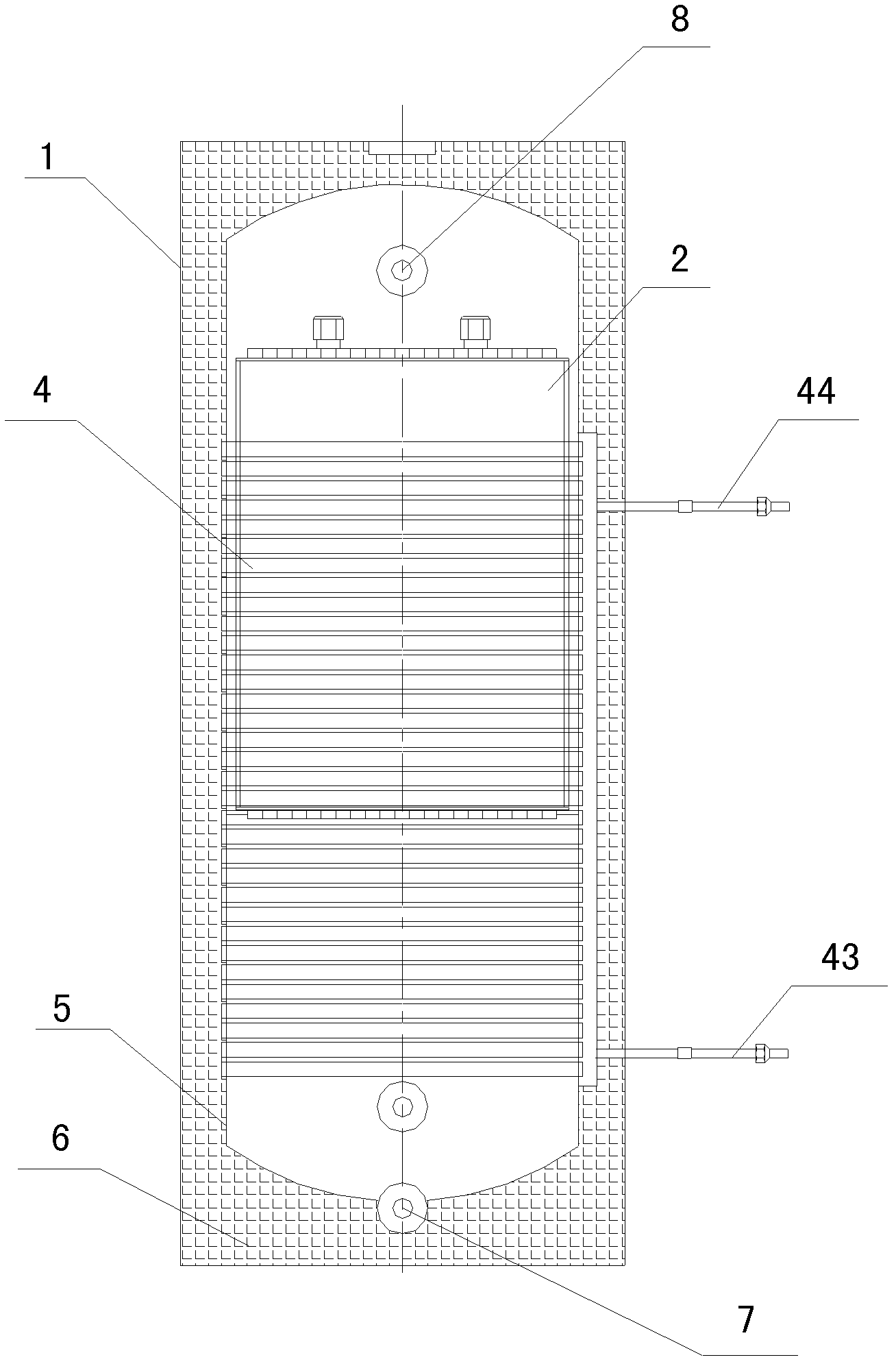
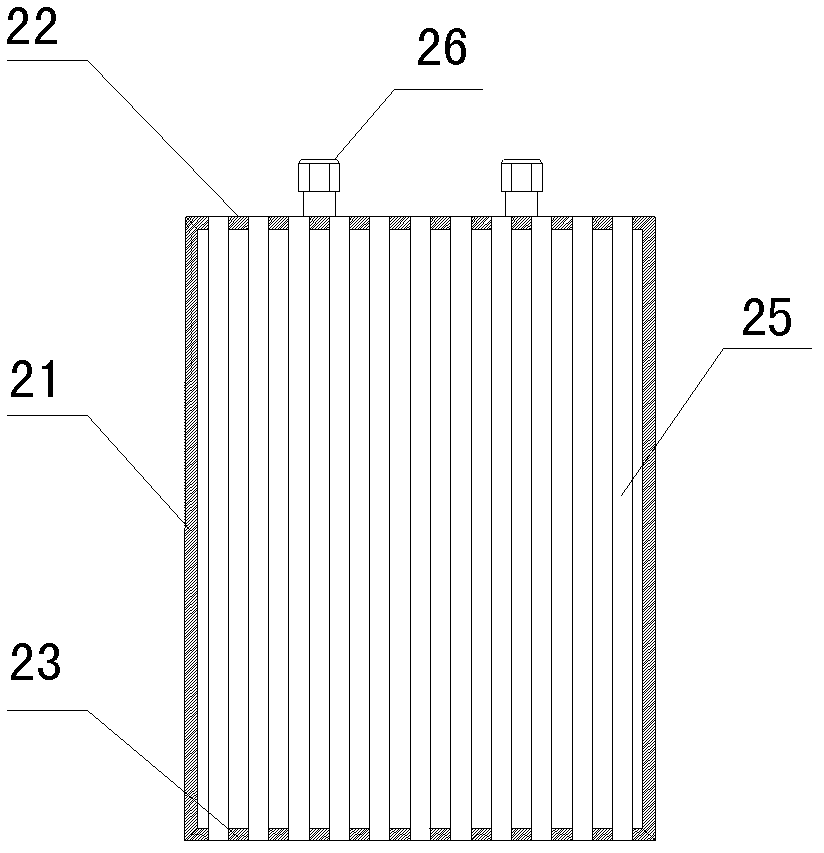
[0030] Such as figure 1 As shown, the hot water storage tank of the present invention includes a shell 1, a heat storage mold box 2, a heat storage material (not shown in the figure), a water tank liner 5, a condensing heat exchanger 4 and a thermal insulation material 6, and the heat storage material The phase change temperature point is between the water temperature of the water inlet and outlet. The heat storage mold box 2 is set inside the water tank liner 5, and the heat insulating material 6 is foamed between the outer shell 1 and the water tank liner 5. On the water tank liner 5 There are inlet and outlet ports 7 and 8. Such as image 3 , 4 As shown, the heat storage mold box 2 includes a cylinder side wall 21 and upper and lower end covers 22, 23, and the upper and lower end covers 22, 23 are provided with vertically opposite small holes 24, and in the vertically opposite two small A connecting pipe 25 is provided between the holes to form a water flow channel conne...

Embodiment 2

[0034] The difference between this embodiment and embodiment 1 is:

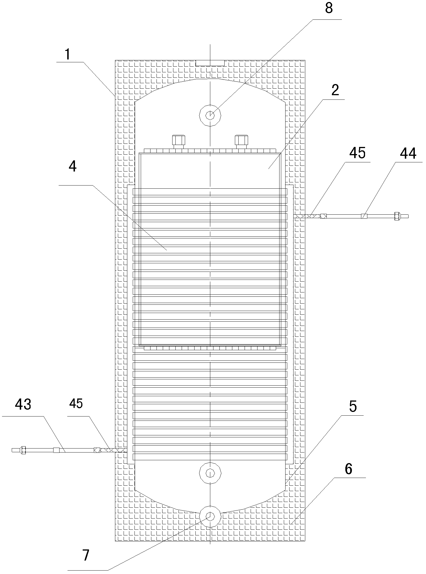
[0035] Such as figure 2 , 7 , 8, the condensing heat exchanger 4 is formed by connecting two microchannel condensers in parallel, the inlet headers 42 of the two microchannel condensers communicate through the refrigerant circulation pipe 45, and the outlets of the two microchannel condensers The headers 46 are communicated through the refrigerant circulation pipes 45, one of which is located at the lower part of the outlet header 46 and communicates with the refrigerant outlet pipe 43, and the other refrigerant circulation pipe is located at the upper part of the inlet header 42 and communicates with the Refrigerant inlet pipe 44.

Embodiment 3

[0037] The difference between this embodiment and embodiment 2 is:

[0038] A groove is arranged on the outer wall of the water tank liner 5, and the flat tube bundle 41 of the microchannel condenser is stuck in the groove.


PUM


Abstract

The invention discloses an outer-disk micro channel type thermal storage water tank for a heat pump water heater, which comprises a casing, a thermal storage molding flask, a thermal storage material, a water tank inner container, a condensation heat exchanger and an insulation material. The thermal storage material is filled in the thermal storage molding flask, the thermal storage molding flask is arranged in the water tank inner container, the insulation material is foamed between the casing and the water tank inner container, and a water inlet / outlet is positioned on the water tank inner container. The thermal storage molding flask comprises a barrel body lateral wall, an upper end cover and a lower end cover, wherein vertically opposite holes are arranged on the upper end cover and the lower end cover, and a communication pipe is positioned between the two vertically opposite holes to form a vertically communicated water flow channel. The thermal storage material is filled outside the communication pipe and in sealed cavities formed by the upper end cover, the lower end cover and the barrel body lateral body. The condensation heat exchanger wraps the outer wall of the water tank inner container. The thermal storage molding flask enables heat exchanger performance between water and the thermal storage material to be remarkably increased. The condensation heat exchanger increases heat exchanger areas and improves systematic heat exchanger efficiency.

Description

technical field [0001] The invention relates to the technical field of refrigeration equipment, in particular to an outer disk microchannel condenser type heat storage tank used for heat pump water heaters. Background technique [0002] The water tank of a heat pump water heater is usually composed of a water tank liner, an insulation layer and a heating pipe (that is, a condenser). For a water tank in which the heater is a circular thin-walled copper tube with an outer disk in the form of a single tube, the contact between the copper tube of the thin-walled heat exchanger and the side of the water tank is the contact between the arc surface and the plane, and the contact area is small. The heat can only be transferred from the refrigerant side to the water inside the water tank through the line contact between the thin-walled copper tube and the inner plane of the water tank. The thermal resistance is large, which seriously affects the heat transfer efficiency and increases...

Claims


Application Information

Patent Timeline
Patent Type & Authority Applications(China)
IPC IPC(8): F24H9/00
Inventor 巫江虹刘超鹏
Owner SOUTH CHINA UNIV OF TECH
Why Eureka
Try Eureka