

Ultra-low-temperature pulse-tube refrigerator, method for operating pulse-tube refrigerator, and rotary valve
A pulse tube and refrigerator technology, applied in refrigerators, multi-way valves, valve devices, etc., can solve the problems of large drive valve torque, large valve disc force, etc., and achieve the effect of reducing the drive torque
- Summary
- Abstract
- Description
- Claims
- Application Information
AI Technical Summary
Problems solved by technology
Method used
Image


Examples
no. 1 Embodiment
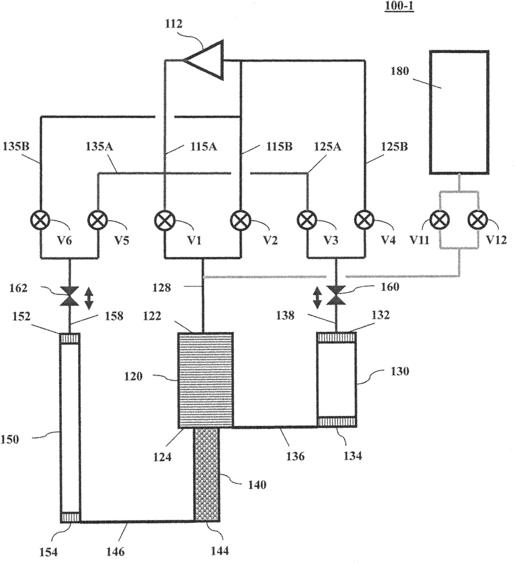
[0048] figure 1 It is a diagram showing the structure of a two-stage four-valve pulse tube refrigerator according to the first embodiment of the present invention. The high-pressure gas Ph flows from the compressor 112 through the first high-pressure piping 115A, the second high-pressure piping 125A, and the third high-pressure piping 135A into the valves V1 , V3 , and V5 . The low-pressure gas P1 returns to the compressor 112 from the valves V2, V4, and V6 through the first low-pressure piping 115B, the second low-pressure piping 125B, and the third low-pressure piping 135B, respectively. The valve V1 controls the airflow flowing into the first regenerator 120 ( R1 ) through the common piping 128 . The valve V2 controls the airflow flowing out from the first regenerator 120 ( R1 ) through the common piping 128 . The valve V3 controls the gas flow flowing into the first-stage pulse tube 130 (PT1) through the common pipe 138 and the first flow path resistance member 160 . Th...
no. 2 Embodiment
[0060] Figure 5 It is a configuration diagram showing a three-stage four-valve type pulse tube refrigerator 200-1 according to the second embodiment of the present invention. The high-pressure gas Ph flows from the compressor 212 through the high-pressure pipes 215A, 225A, 235A, and 245A into the valves V1 , V3 , V5 , and V7 . The low-pressure gas P1 returns to the compressor 212 from the valves V2, V4, V6, and V8 through the low-pressure piping 215B, 225B, 235B, and 245B. The valve V1 controls the airflow flowing into the first regenerator 220 ( R1 ) through the common piping 228 . The valve V2 controls the airflow flowing out from the first regenerator 220 ( R1 ) through the common piping 228 . The valve V3 controls the airflow flowing into the first-stage pulse tube 230 (PT1) through the common pipe 238 and the first flow path resistance member 260 . The valve V4 controls the airflow flowing out from the first-stage pulse tube 230 (PT1) through the common pipe 238 and t...
no. 3 Embodiment
[0068] Figure 8 It is a configuration diagram showing a single-stage four-valve pulse tube refrigerator 300-1 according to a third embodiment of the present invention. The high-pressure gas Ph flows from the compressor 312 through the high-pressure pipes 315A and 325A into the valves V1 and V3. The low-pressure gas P1 is returned to the compressor 312 from the valves V2 and V4 through the low-pressure piping 315B and 325B. The valve V1 controls the airflow flowing into the first regenerator 320 ( R1 ) through the common piping 328 . The valve V2 controls the airflow flowing out from the first regenerator 320 ( R1 ) through the common piping 328 . The valve V3 controls the air flow flowing into the first-stage pulse tube 330 (PT1) through the common pipe 338 and the first flow path resistance member 360 . The valve V4 controls the airflow flowing out from the first-stage pulse tube 330 (PT1) through the common pipe 338 and the first flow path resistance member 360 . Valve ...
PUM
 Abstract
Description
Claims
Application Information