
In-vivo remote intrathecal injection method

A technology for intrathecal injection and syringes, applied in the field of syringes, can solve the problems of cumbersome operation, intrathecal infection of rats, and high requirements for aseptic conditions, and achieve the effect of convenient injection volume and convenient control

Inactive Publication Date: 2015-01-14
FOURTH MILITARY MEDICAL UNIVERSITY
View PDF4 Cites 0 Cited by
  • Summary
  • Abstract
  • Description
  • Claims
  • Application Information

AI Technical Summary

Problems solved by technology

1) Easy to infection Because the outer end of the intrathecal tube is repeatedly opened, the injection requires high aseptic conditions, and the rats are prone to intrathecal infection and death; 2) The rats are repeatedly stimulated and frightened, and the synaptic signal transmission may change , affecting the interpretation of experimental results; 3) repeated inhalation of anesthesia, affecting the interpretation of experimental results; 4) cumbersome operation, which is not conducive to dynamic analysis of drug efficacy

Method used


Image

  • In-vivo remote intrathecal injection method
  • In-vivo remote intrathecal injection method
  • In-vivo remote intrathecal injection method

Examples


Embodiment 1

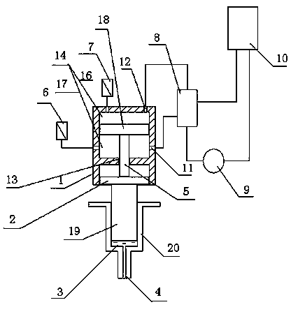
[0019] like figure 2 As shown, the remote control injection body 21 includes the piston body 1 and the syringe body 20, the lower end of the syringe body 20 is the syringe liquid outlet 4, and the piston chamber 14 of the piston body 1 is divided into an upper chamber 16 by a piston 18. And lower chamber 17, upper chamber 16 and lower chamber 17 have gas input / output port 11 and gas output / input port 12 respectively. The gas input / output port 11 can be the gas input port or the gas output port; similarly, the gas output / input port 12 can be the gas output port or the gas input port; the lower end of the syringe piston 2 extends into the syringe tube The injection chamber 3 of the body 20, the injection chamber 3 sucks the injection through the syringe outlet 4; the upper chamber 16 has a pressure sensor interface, and the pressure sensor 7 is connected through the pressure sensor interface; the lower chamber 17 has a displacement sensor interface, through which the displaceme...

Embodiment 2

[0023] like Figure 4 As shown, the remote control injection tube 21 is composed of the piston tube 1 and the syringe tube 20, the piston tube 1 and the syringe tube 20 are integrated tube structure, and the tube is divided into the piston chamber 14 and the injection liquid chamber by the sealing port 13 15. The lower end of the injection chamber 15 is the syringe liquid outlet 4. The piston chamber 14 divides the chamber into an upper chamber 16 and a lower chamber 17 through a piston 18. The upper chamber 16 and the lower chamber 17 have air input / output ports 11 and air outlets respectively. Output / Input port 12. The gas input / output port 11 can be the gas input port or the gas output port; similarly, the gas output / input port 12 can be the gas output port or the gas input port; the injection chamber 15 has Syringe piston 2, the injection liquid chamber 3 is formed at the lower end of the syringe piston 2, and the injection liquid chamber 3 sucks the injection liquid thro...


PUM


Abstract

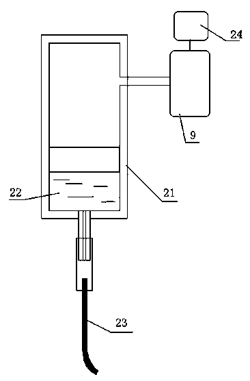
The invention relates to an injector, in particular to an in-vivo remote intrathecal injection method. The injector at least comprises a remote injection pipe body (21), wherein injection (22) is filled into the remote injection pipe body (21); an injection port of the remote injection pipe body (21) is connected with an injection pipe (23) and a pump unit (9); the pump unit (9) is electrically connected with a wireless control unit (24); the wireless control unit (24) receives a wireless control signal and controls the pump unit (9) to work; and the remote injection pipe body (21) outputs the injection (22) through the injection pipe (23). The in-vivo remote intrathecal injection method is high in safety and convenient in use and is applied to liquid inlet volume control of a laboratory.

Description

technical field [0001] The invention relates to a syringe, in particular to an in-body remote-controlled intrathecal injection method, which is used to control the amount of liquid ingested in a laboratory. Background technique [0002] It is one of the commonly used methods in neuropharmacology research to infuse drugs directly into the dorsal horn of rat spinal cord by intrathecal catheter. The currently widely used intrathecal tube method is based on the report by Yaksh et al. (Yaksh and Rudy, 1976) and some related improved methods (LoPachin, et al., 1981; Wu, et al., 2004). The common point of these methods is to embed a catheter in the rat sheath by surgical method, fix the tail end of the catheter under the skin of the rat and extend it out of the body. When performing drug injection, first the rats are anesthetized by inhalation, the tail end of the catheter is opened, and a microinjector is connected for injection. After the injection, another 10 μl of normal sali...

Claims


Application Information

Patent Timeline
Patent Type & Authority Patents(China)
IPC IPC(8): A61D7/00
Inventor 王文朱超孙莉莉高昌俊每晓鹏董玉琳陈磊李辉武胜昔李云庆
Owner FOURTH MILITARY MEDICAL UNIVERSITY
Learn More