Inflation tire

A technology for pneumatic tires and tires, which is applied to tire parts, tire tread/tread pattern, transportation and packaging, etc. It can solve the problems of difficulty, deterioration of wet road performance, and easy reduction of residual CF, and achieve uniform rigidity Effect

Inactive Publication Date: 2012-08-29
SUMITOMO RUBBER IND LTD
View PDF9 Cites 16 Cited by
  • Summary
  • Abstract
  • Description
  • Claims
  • Application Information

AI Technical Summary

Problems solved by technology

[0003] However, the above-mentioned method has a problem of deterioration of wet performance due to reduction of groove volume or edge components.
In addition, in order to prevent the vehicle from skidding on the main road surface (such as a sloped road surface for drainage), it is necessary to ensure a large residual lateral resistance force (hereinafter, sometimes simply referred to as "residual CF"), but the above method has residual CF. easily reduced problem
In this way, there is a contradictory relationship between improving heel-toe wear resistance and ensuring wet performance and sideslip performance, and it is difficult to make them coexist

Method used


Image

  • Inflation tire
  • Inflation tire
  • Inflation tire

Examples


Embodiment

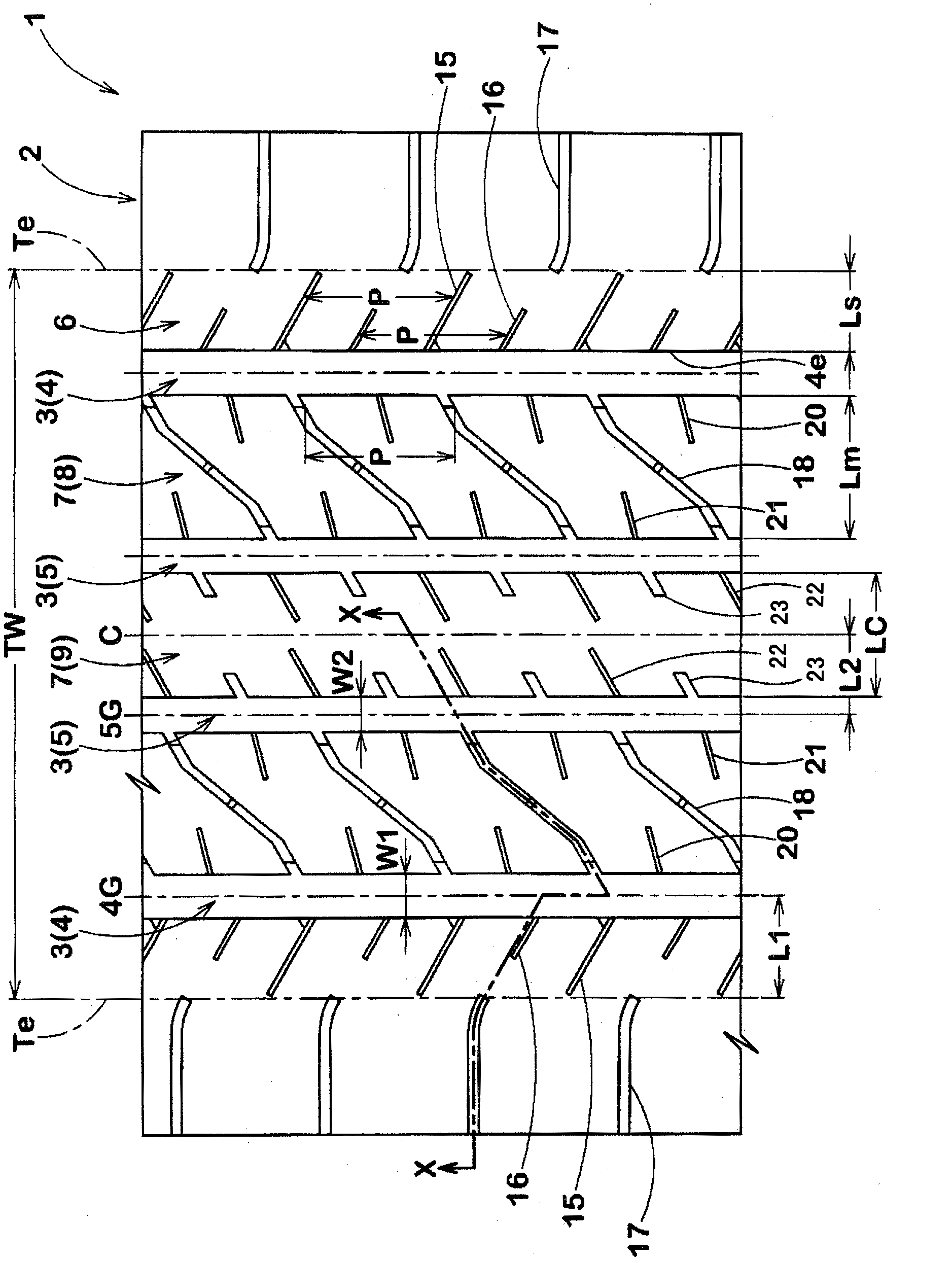
[0059] Manufacturing has figure 1 Pneumatic tires (size: 215 / 55R17) with a tread pattern based on the specifications in Table 1, and their performances were tested. Among them, the common specifications are as follows.

[0060] Rim size: 7J

[0061] Tread contact width: 170mm

[0062]

[0063] Groove width W1 / Tread contact width TW: 4.5%

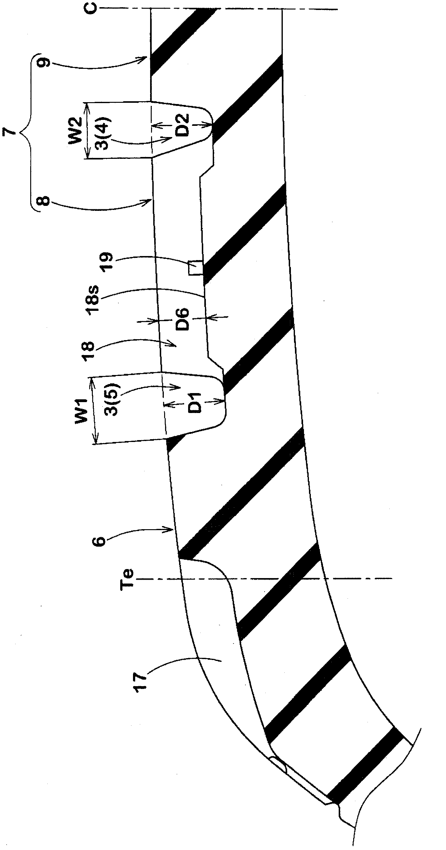
[0064] Groove depth D1: 8.2mm

[0065] Angle relative to tire equator C: 0 degrees

[0066] Installation location: L2 / TW from tire equator C

[0067]

[0068] Groove width W2 / Tread contact width TW: 4.9%

[0069] Groove depth D2: 8.2mm

[0070] Angle relative to tire equator C: 0 degrees

[0071]

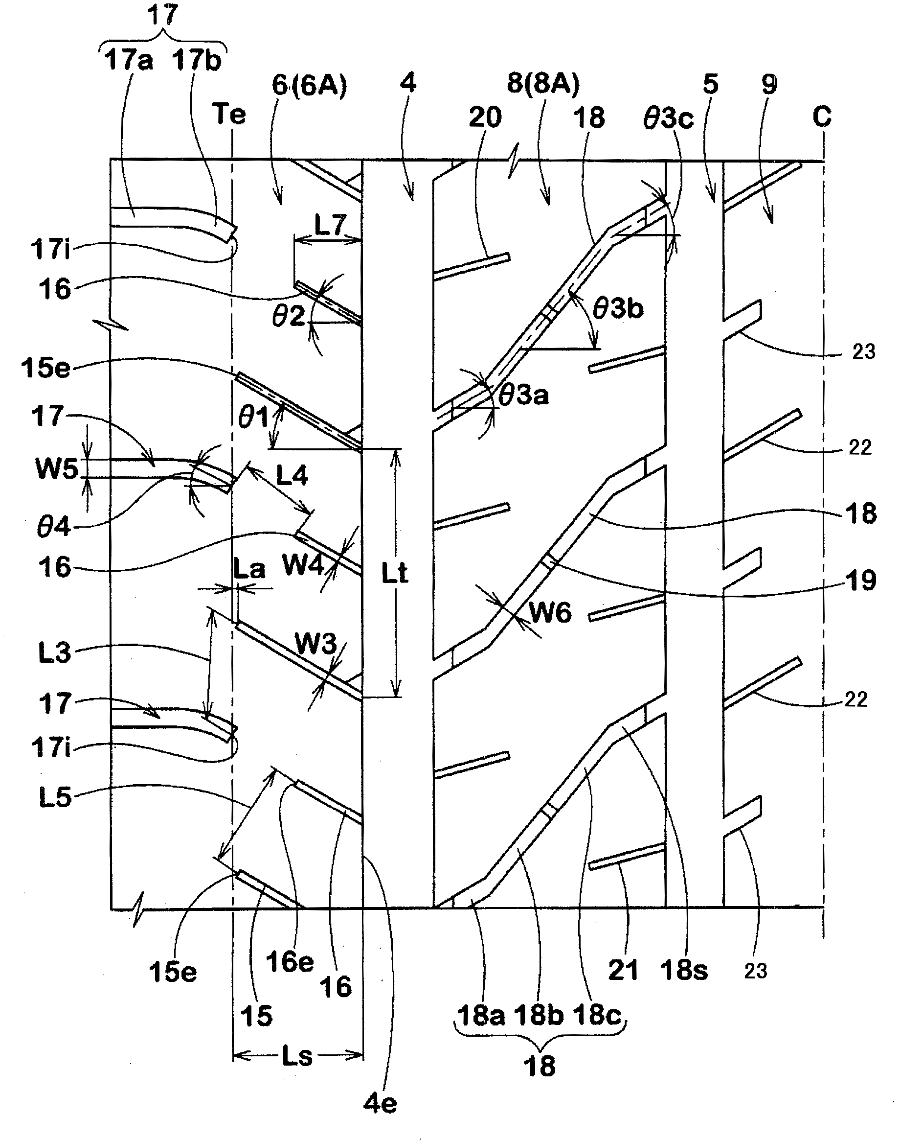
[0072] Groove width W3: 0.8mm

[0073] Ditch depth D3: 6.0mm

[0074]

[0075] Groove width W4: 0.6mm

[0076] Groove depth D4: 6.0mm

[0077] Tire axial length L7 / Ls: 40%

[0078]

[0079] Groove width W5: 2.0mm

[0080] Groove depth D5: 6.6mm

[0081]

[0082] Groove width W6: 2.0mm

[0083] Groove depth D6: 6.0mm

...


PUM


Abstract

The invention discloses an inflation tire, which can be used to maintain the sideslipping performance, the performance on wet road surfaces of the vehicle, and to improve the heal-and-toe wear resistance performance of the vehicle. The inflation tire (1) is provided with a plurality of grooves(3) of a pair of tire shoulder main grooves(4). A land part width (Ls) of a tire shoulder land part(6) is 10 to 15% of a tire surface grounding width (TW). The tire shoulder land part (6) is provided with a first tire shoulder horizontal groove (15), which extends from the part close to the tire surface grounding end (Te),and is inclined at an angle of 10 to 35 degrees relative to the tire shaft; a second tire shoulder horizontal groove (16), which is inclined from the part between the first tire shoulder horizontal grooves (15, 15) at an angle of 10 to 35 degrees towards the axial direction of the tire, and can form a terminal on the tire shaft more close to the inner side than the first tire shoulder horizontal groove(15); a third tire shoulder horizontal groove (17), which is inclined from the outer side of the tire surface grounding end (Te) of the tire shaft towards the inner side of the tire shaft, and can form a terminal close to the tire surface grounding end(Te).

Description

technical field [0001] The present invention relates to a pneumatic tire that maintains the sideslip performance, wet road performance, etc. of a vehicle and improves heel-toe wear resistance. Background technique [0002] In the past, a plurality of blocks were formed on the tread portion, but in recent years blocks have been required to improve heel-toe wear resistance. In order to improve heel-toe wear resistance, it is known to enlarge the pattern by reducing the depth, groove width and / or number of arrangement of the lateral grooves that divide the blocks, especially the shoulder lateral grooves provided on the tread contact end side. A method such as pattern rigidity of the block. [0003] However, the above method has a problem of deterioration of wet performance due to reduction of groove volume and edge components. In addition, in order to prevent the vehicle from skidding on the main road surface (such as a sloped road surface for drainage), it is necessary to en...

Claims


Application Information

Patent Timeline
Patent Type & Authority Applications(China)
IPC IPC(8): B60C11/117
CPCB60C11/03B60C11/033B60C2011/0358B60C2011/0365
Inventor 岩井义孝
Owner SUMITOMO RUBBER IND LTD
Why Eureka
Try Eureka