Shift register and grid line driving device

A shift register and gate technology, applied in static memory, digital memory information, instruments, etc., can solve the problems of signal output output noise interference, wrong output high level, leakage current increase, etc., to reduce noise interference Effect

Active Publication Date: 2012-08-29
BEIJING BOE OPTOELECTRONCIS TECH CO LTD
View PDF4 Cites 70 Cited by
  • Summary
  • Abstract
  • Description
  • Claims
  • Application Information

AI Technical Summary

Problems solved by technology

[0005] It can be seen from the working process of the above shift register that the gate of the thin film transistor M3 and the signal output terminal Output are in a floating state during non-working hours. When the clock signal terminal is at a high lev

Method used


Image

  • Shift register and grid line driving device
  • Shift register and grid line driving device
  • Shift register and grid line driving device

Examples


Embodiment Construction

[0039] The shift register and the gate line driving device according to the embodiments of the present invention will be described in detail below with reference to the accompanying drawings.

[0040] It should be clear that the described embodiments are only some of the embodiments of the present invention, not all of them. Based on the embodiments of the present invention, all other embodiments obtained by persons of ordinary skill in the art without creative efforts fall within the protection scope of the present invention.

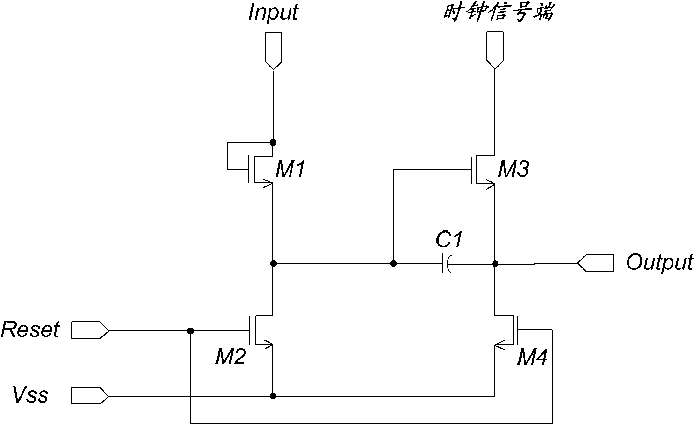
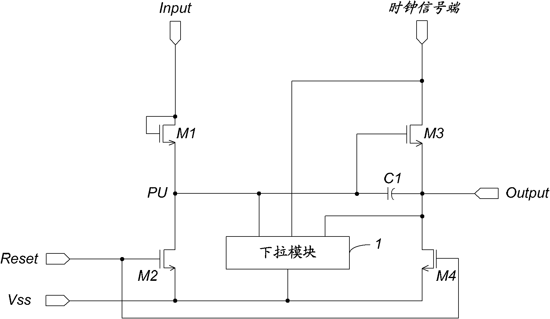
[0041] Such as image 3 Shown is a schematic diagram of the shift register of the embodiment of the present invention. The shift register in this embodiment includes four thin film transistors, a storage capacitor, a pull-down module and corresponding input and output terminals. Specifically include:

[0042]The first thin film transistor M1 has its gate and drain connected together to the signal input terminal Input, and its source is connected to ...


PUM


Abstract

The invention discloses a shift register and a grid line driving device, which relate to the technical field of liquid crystal display. In order to reduce noise jamming of the shift register at the standby unattended time, the shift register and the grid line driving device are invented. The shift register comprises a first thin film transistor, a second thin film transistor, a third thin film transistor, a fourth thin film transistor, a capacitor and a drop-down module, wherein the drop-down module connected among a clock signal end, a first node and a signal output end is connected with a low level signal end and used for maintaining the first node and the signal output end to have a low level at the standby unattended time of the shift register. The grid line driving device comprises a plurality of the shift registers which are connected in series. The grid line driving device can be used for driving a grid line.

Description

technical field [0001] The invention relates to the technical field of liquid crystal display, in particular to a shift register and a gate line driving device. Background technique [0002] The pixel array of the liquid crystal display panel includes multiple rows of gate lines and multiple columns of data lines. Wherein, the driving of the gate line can be realized through the attached integrated driving circuit, so it is necessary to reserve a certain area at the edge of the array substrate of the liquid crystal display panel as the bonding (Bonding) area of ​​the integrated driving circuit and the array substrate. The fan-out (Fan-out) wiring area of ​​the upper gate line. Then the integrated driving circuit can be bound on the array substrate through a flexible circuit board COF (Chip On FPC). [0003] It can be seen that, when using the integrated driving circuit to drive the gate lines, since a certain area needs to be reserved at the edge of the array substrate, th...

Claims


Application Information

Patent Timeline
IPC IPC(8): G09G3/20G09G3/36
CPCG09G2310/0286G11C19/28G09G3/36G11C19/00G09G3/3674
Inventor 陈希崔文海
Owner BEIJING BOE OPTOELECTRONCIS TECH CO LTD
Why Eureka
Try Eureka