
Driving circuit for LED

A technology of driving circuits and zener diodes, which is applied in the layout of electric lamp circuits, light sources, electric light sources, etc., can solve the problems of matching specifications and design bottlenecks and other problems, and achieve the effect of promoting industrial development, bright life, and improving utilization rate.

Inactive Publication Date: 2012-08-29
HANERGY TECH
View PDF3 Cites 21 Cited by
  • Summary
  • Abstract
  • Description
  • Claims
  • Application Information

AI Technical Summary

Problems solved by technology

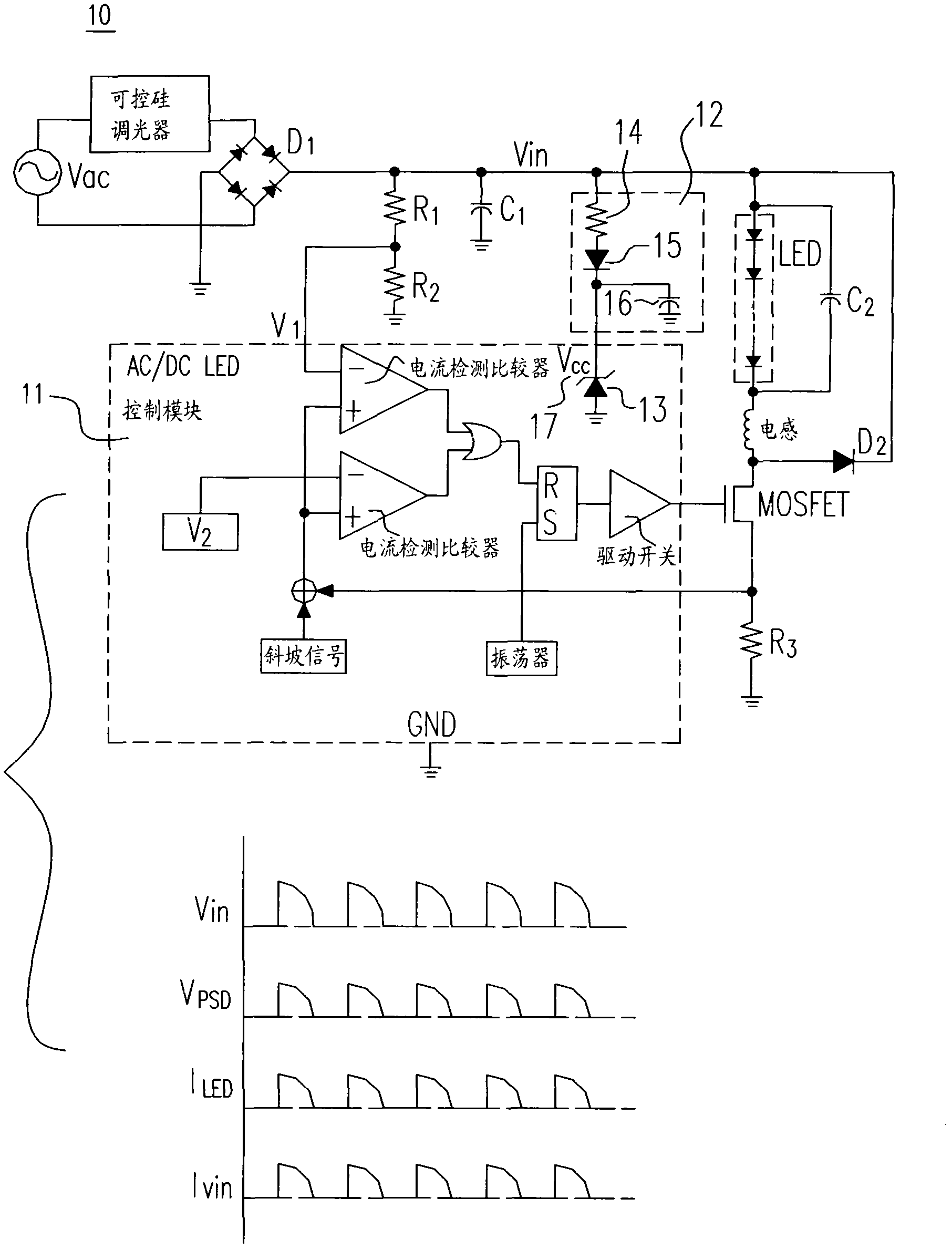
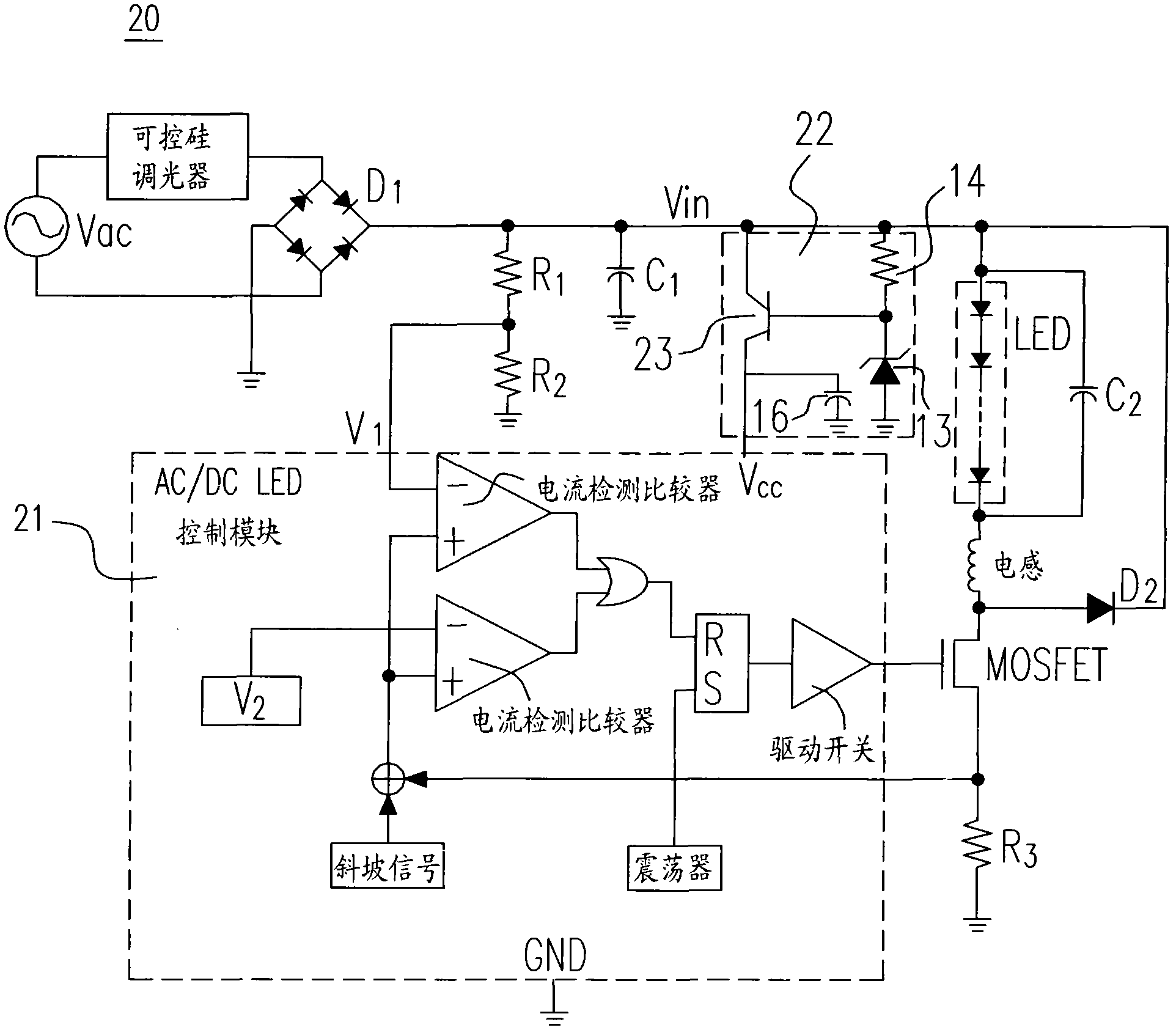
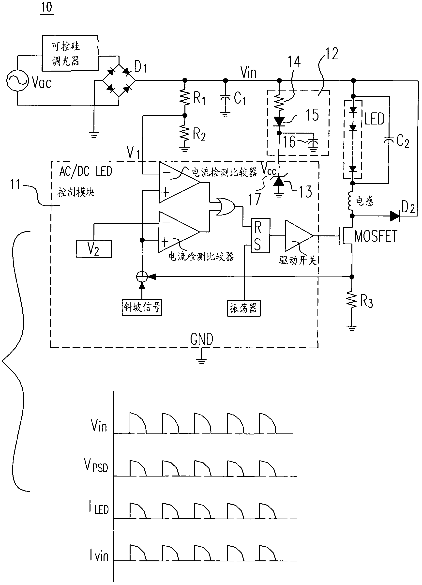
However, because the multiple components in the drive control modules 11 and 21 cannot operate on a stable ground plane, the matching specifications of the multiple components are likely to cause a design bottleneck, which in turn leads to the LED drive switch of the control modules 11 and 21 The output control signal of the power supply fails to help the power supply to save power

Method used


Image

  • Driving circuit for LED
  • Driving circuit for LED
  • Driving circuit for LED

Examples


Embodiment

[0050] 1. A driving circuit device, comprising:

[0051] a control module providing control signals to regulate load current flowing through the load; and

[0052] The voltage clamping module provides the power supply voltage to the control module.

[0053] 2. The driving circuit device according to the first embodiment, wherein the voltage clamping module includes:

[0054] Zener diode, as a voltage source to provide a stable voltage function;

[0055] first resistance;

[0056] a diode connected to the first resistor and the Zener diode; and

[0057] The first capacitor is connected to the diode, wherein when there is no input voltage, the first capacitor provides the power supply voltage to the control module.

[0058] 3. The driving circuit device according to the second embodiment, wherein the Zener diode determines the power supply voltage provided to the control module.

[0059] 4. The driving circuit device according to the second embodiment, wherein the first res...


PUM


Abstract

The invention discloses a driving circuit for a LED which can provide a stable voltage source for a control module of the driving circuit to obtain a stable running stat of the driving circuit. According to traditional technology, an AC input end of a driving circuit for a LED is provided with a triac dimmer to half reduce inputted wave energy, which may lead to the case that in a period when input periodic wave has no energy, the control module can periodically locate at a low potential to cause failure of inner components; thereby the invention provides a control module which can continuously provide a power source voltage for the driving circuit for a LED, which is benefit for the application and popularization of the driving circuit for a LED and sets an example for present light display element drive circuit.

Description

technical field [0001] The invention relates to a driving circuit, in particular to a driving circuit of an LED. By providing a stable voltage source to the control module of the driving circuit, the stable working mode of the driving circuit is achieved. Background technique [0002] The driving circuit of light-emitting diode (LED) has always been the focus of discussion in electronics and electricity. Recently, in view of the complete production process of luminescent materials and the strong demand in the global market, how to achieve design technology that meets the product life cycle has become a research hotspot. [0003] Light-emitting diodes (LEDs) have been in the market for a long time. At first, they were only used as red indicator lights, and then yellow, orange, green, and blue LEDs appeared at the latest to greatly expand the application level, including traffic lights, car lights, etc. And wall lighting (ambient lighting) and LED array fluorescent lamps and ...

Claims


Application Information

Patent Timeline
Patent Type & Authority Applications(China)
IPC IPC(8): H05B37/02
CPCH05B45/3725H05B45/375
Inventor 张钦奇张荣璋
Owner HANERGY TECH
Learn More