Low power consumption remote awakening intelligent lock system

A remote wake-up and smart lock technology, applied in signal transmission systems, building locks, lock applications, etc., can solve the problems of reducing battery life and wasting power consumption of smart locks, so as to prolong battery life, improve competitiveness, Effect of Reducing Operating Power Consumption

Inactive Publication Date: 2012-09-05
HANGZHOU SHTECH
View PDF5 Cites 28 Cited by
  • Summary
  • Abstract
  • Description
  • Claims
  • Application Information

AI Technical Summary

Problems solved by technology

But in fact, under normal use, the possibility of the smart key sending a signal is relatively small, and the way of always opening or opening at intervals will waste a lot of power consumption of the smart lock and reduce the service life of the battery

Method used


Image

  • Low power consumption remote awakening intelligent lock system
  • Low power consumption remote awakening intelligent lock system
  • Low power consumption remote awakening intelligent lock system

Examples


Embodiment 1

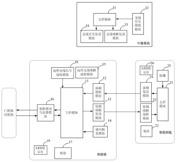
[0028] Embodiment 1: with reference to attached Figure 1-10 . A special smart lock system for home use, including three parts: smart lock, smart key and relay module. The smart lock basic system includes at least a main control module 11, a high-frequency receiving module 12, a low-frequency wake-up sending module 13, and a sensing trigger module 14. Motor drive and feedback module 16, remote wireless signal receiving module 18 and remote wireless wake-up receiving module 15, wherein the main control module 11 of the smart lock is connected to the motor drive and feedback module 16, which drives the motor on the one hand and receives motor feedback on the other hand signal; the low-frequency signal output end of the lock main control module 11 is connected to the input end of the low-frequency wake-up sending module 13, and sends a wireless low-frequency wake-up signal to wake up the smart key; Frequency ID signal, demodulates the high-frequency signal and sends it to the lo...

Embodiment 2

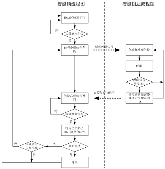
[0041] Embodiment 2: On the basis of Embodiment 1, a working method of a home-use smart lock, smart key, and relay module, the work flow of the smart lock and smart key in normal working mode is as attached figure 2 shown. In the initial state, both the smart lock and the smart key are in a low power consumption state; when the human body touches the trigger sensing module 14, the trigger sensing module 14 sends a signal to the lock main control module 11, and the lock main control module 11 exits the low power consumption mode and Wake up the sending module 13 by low frequency (the schematic diagram is as follows Figure 9 ) to wake up the smart key by sending the agreed data, after which the smart lock enters the state of waiting for high-frequency data, the lock main control module 11 opens the high-frequency receiving module 12 and monitors the data from the high-frequency channel, at the same time, when the low-frequency signal covers The smart key within the range is i...

example 1

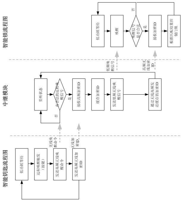
[0043] Example 1: Workflow as attached image 3 shown. In the initial state, both the smart lock and the smart key are in a low power consumption state, and the relay module is in a working state; The wireless receiving module 32 of the relay module receives a wake-up command in a legal format (the command format is customized by the manufacturer), and then waits for the smart key to send an encrypted ID. After the relay module receives the encrypted ID sent by the key, it temporarily caches the encrypted ID. The relay module sends a wireless low-frequency remote wake-up signal to the remote wireless wake-up module 15 of the smart lock through the wireless low-frequency wake-up module 33, after which the smart lock system is woken up and ready to receive the encrypted ID. The relay module then sends the temporarily cached encrypted ID to the smart lock system. The core essence of this method is that the smart key can directly send a wake-up command and an encrypted ID, whic...


PUM


Abstract

The invention relates to a remote awakening low power consumption intelligent lock. The intelligent lock system designs a remote wireless awakening trigger module and a remote wireless signal receiving module on the basis of a traditional keyless entry intelligent door lock, and a master control module is in a low power consumption state in a non-working state. A relay module is always in a working mode for monitoring a high-frequency channel, after a high-frequency awakening command sent by a key is received, the intelligent lock system is firstly awakened through a wireless awakening signal, and then the intelligent lock starts to receive an encrypted ID (identification) signal. The working way can enable the intelligent lock with a remote unlocking function to effectively prolong the service time of a battery.

Description

technical field [0001] The invention relates to a low-power intelligent lock with a remote wake-up function. After a relay module in a listening state receives a wake-up signal from a smart key, it actively wakes up the smart lock system through a low-frequency wake-up signal and communicates with it. It belongs to the field of smart lock and smart key manufacturing. Background technique [0002] The door lock is the security line of defense of the home, and it is a system that people must use every day to enter and exit the house. From the perspective of application, the intelligent door lock system is the starting point of the design of smart home. The main design goal of the smart door lock is to improve the security of the key and the convenience of use. At present, the smart door locks in the market mainly include smart card door locks, fingerprint door locks and keyless entry door locks. Smart card door locks identify various forms of cards in the hands of users thr...

Claims


Application Information

Patent Timeline
Patent Type & Authority Applications(China)
IPC IPC(8): E05B49/00E05B19/00G08C17/02
Inventor 华林阮宏鸣
Owner HANGZHOU SHTECH
Why Eureka
Try Eureka