Oil pressure rod device for manual power tool

A technology for power tools and hydraulic rods, which is applied to the field of hydraulic rod devices assembled and produced, can solve the problems of external gas entry, insufficient retraction force, poor wall uniformity, etc., and achieves the difficulty of convenient disassembly and simplified assembly. Effect

Inactive Publication Date: 2014-08-27
王明郁
View PDF9 Cites 0 Cited by
  • Summary
  • Abstract
  • Description
  • Claims
  • Application Information

AI Technical Summary

Problems solved by technology

[0004] However, since the main body 1 of the oil pressure rod is integrated, its hydraulic oil groove 2 is a deep hole in the processing process. , it is easy to produce tool marks on the wall of the hydraulic oil tank 2 due to the vibration of the machine operation, and when the hydraulic oil tank 2 is polished and ground, the closer to the closed end of the wall of the hydraulic oil tank 2, the more difficult it is to grind, resulting in the input piston 5 When pushing the hydraulic oil, it is easy to cause problems such as oil leakage and insufficient output force due to the poor uniformity of the wall surface of the hydraulic oil tank 2. Uneven edges are generated at the junction of the power screw hole 4, because it is difficult to trim because it is located inside the deep hole, and the above problems are more likely to occur
And when the input shaft 3 is withdrawn, it will cause external air to enter the hydraulic oil tank 2, resulting in insufficient withdrawal force, and the output shaft 6 cannot be driven back by the spring 9 alone.
[0005] Furthermore, the integrated design of the main body 1 of the oil pressure rod results in that all internal parts need to be assembled from the square end, relatively speaking, it will make it difficult to assemble the parts related to the input shaft 3, and if the assembly accuracy is not good , all the parts on the side of the output shaft 6 must be removed before disassembling the parts on the side of the input shaft 3, which increases the difficulty of production, manufacturing and quality inspection

Method used


Image

  • Oil pressure rod device for manual power tool
  • Oil pressure rod device for manual power tool
  • Oil pressure rod device for manual power tool

Examples


Embodiment Construction

[0033] For ease of explanation this case expresses in the above-mentioned content of the invention column central thought, hereby expresses with specific embodiment. Various objects in the embodiments are drawn in proportions suitable for illustration rather than actual components, and are described first.

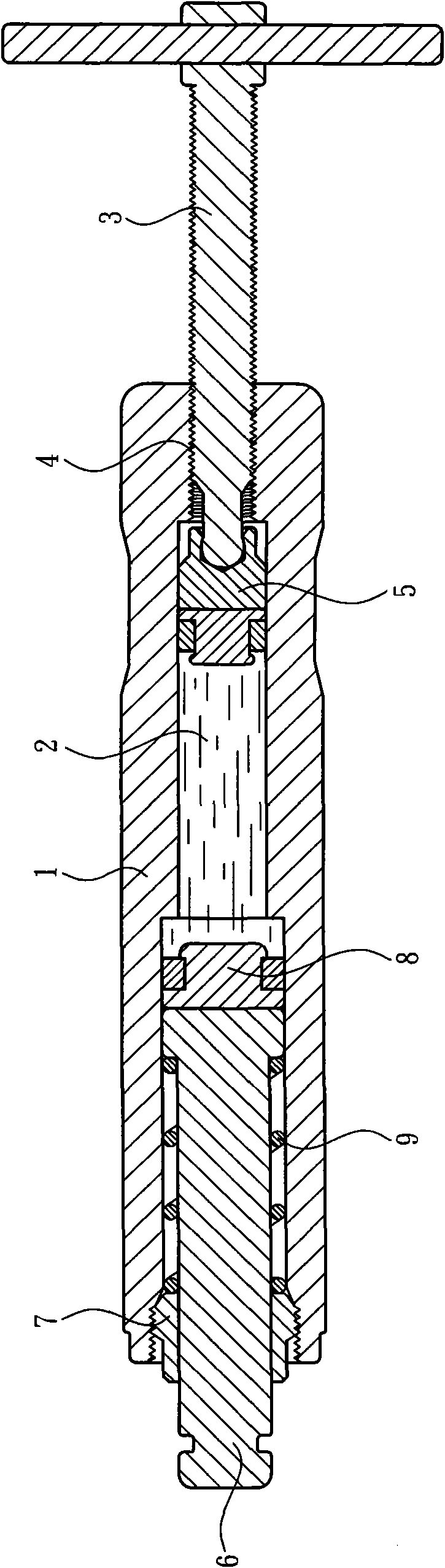
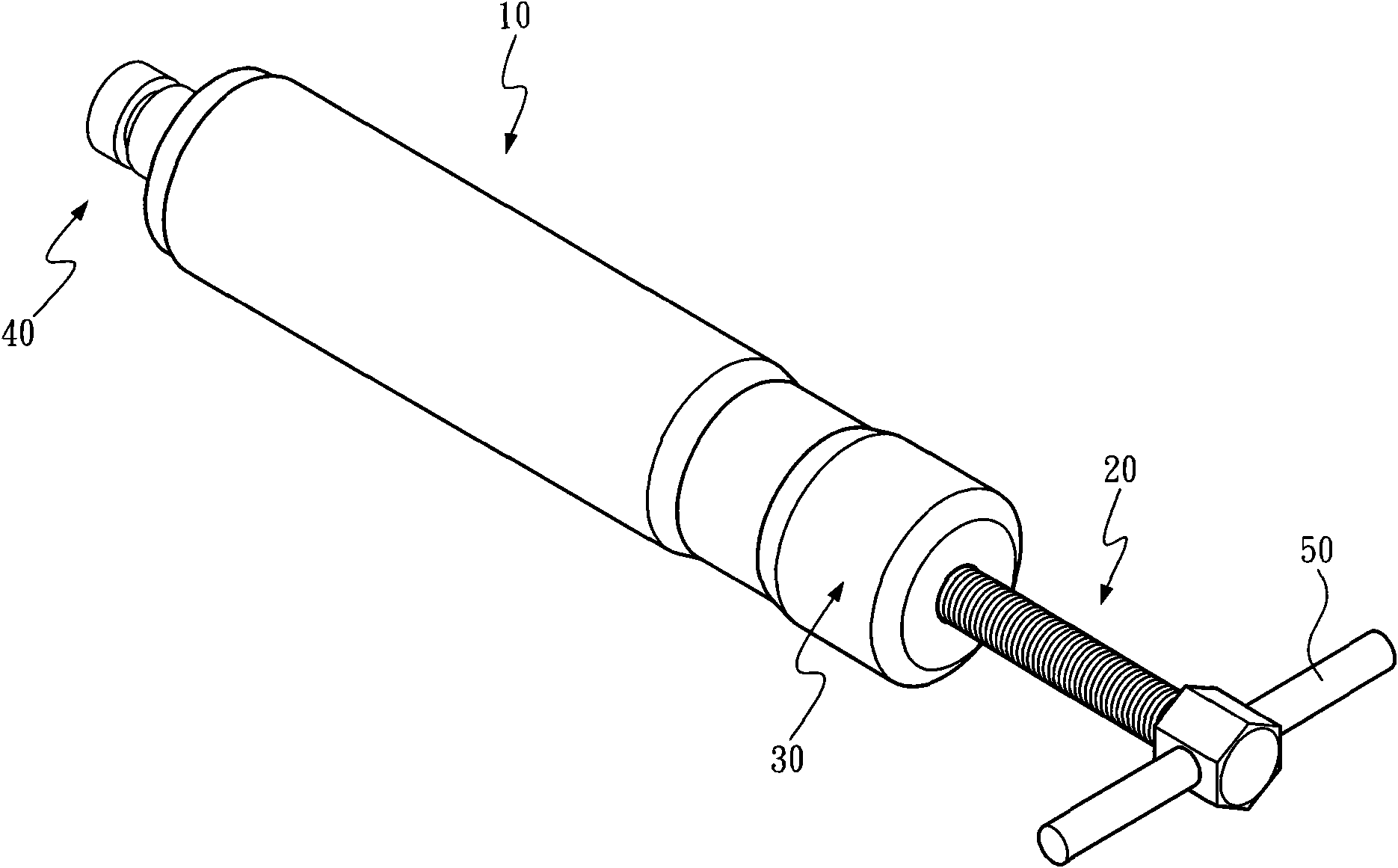
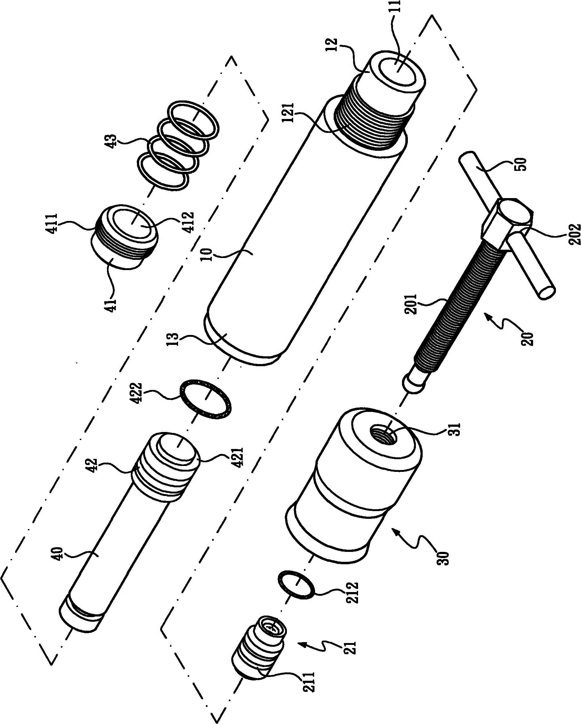
[0034] Such as Figure 2 ~ Figure 4 As shown in the drawing, the present invention is an oil pressure rod device of a manual power tool, which mainly includes:

[0035] An oil pressure rod main body 10 has a through hydraulic oil tank 11 inside, the hydraulic oil tank 11 can store hydraulic oil, and the two ends of the oil pressure rod main body 10 are respectively an input end 12 and an output end 13; The outer edge ring of the input end 12 is provided with an engaging thread segment 121;

[0036] An input shaft 20, which passes through the input end 12, an input piston 21 is provided at one end of the input shaft 20 opposite to the hydraulic oil tank 11, and at least o...


PUM


Abstract

The invention provides an oil pressure rod device for a manual power tool. The oil pressure rod device mainly comprises an oil pressure rod main body, an input shaft, an input end cover and an output shaft, wherein a through hydraulic oil slot is arranged in the oil pressure rod main body; two ends of the pressure rod main body are respectively provided with an input end and an output end; the input shaft is arranged at the input end in a penetrating manner; the input shaft is provided with an external thread section; the input end cover is screwed at the input end; the center of the input end cover is provided with a power screw hole in a penetrating manner for the external thread section to be movably screwed; the output shaft is arranged at the output end in a penetrating manner; the output end and the output shaft are sealed and sheathed by a fixing nut; and one end of the output shaft, which penetrates out of the oil pressure rod main body, can be assembled for a manual tool. The hydraulic oil slot can be polished and grinded by the oil pressure rod main body and the input end cover which are independently arranged, so that the problems of the hydraulic leakage and insufficient output force caused by poor tightness can be avoided. In addition, the oil pressure rod device is convenient to assemble and produce.

Description

technical field [0001] The present invention is related to the oil pressure rod device of manual power tools. More specifically, it refers to an oil pressure rod device that can prevent problems such as hydraulic leakage and insufficient output force caused by poor adhesion, and is more convenient for assembly and production. . Background technique [0002] Commonly used manual power tools, such as the disassembly and assembly tools used to disassemble automobile calipers and other parts, because the parts themselves require a large force output and are affected by the limitation of internal space, most of them use manually driven hydraulic cylinders as the power source, such as figure 1 A conventional one-piece oil pressure rod device shown in the figure has a hydraulic oil tank 2 for oil storage in a hydraulic rod main body 1, and the oil pressure rod main body 1 has a closed end and an open end , the closed end is pierced with a power screw hole 4 for an input shaft 3 to...

Claims


Application Information

Patent Timeline
Patent Type & Authority Patents(China)
IPC IPC(8): F15B15/08B23P19/027
Inventor 王明郁
Owner 王明郁
Why Eureka
Try Eureka