Infrared analysis apparatus

An analysis device, infrared technology, applied in the direction of measuring device, material analysis, material analysis through optical means, etc., can solve the problem of uneven intensity distribution and achieve the effect of uniform intensity distribution and high measurement accuracy

Active Publication Date: 2012-09-05
YOKOGAWA ELECTRIC CORP
View PDF22 Cites 12 Cited by
  • Summary
  • Abstract
  • Description
  • Claims
  • Application Information

AI Technical Summary

Problems solved by technology

The former method superimposes the near-infrared light emitted from each converging optical system at the same position on the inspection object, but even if the superimposition is performed, the intensity distribution is not uniform
In the latter method, the diameters (spot diameters) of various near-infrared lights emitted from the condensing optical system and irradiated on the inspection object are different for each wavelength, and the intensity distribution is not uniform.

Method used


Image

  • Infrared analysis apparatus
  • Infrared analysis apparatus
  • Infrared analysis apparatus

Examples


Embodiment Construction

[0024] Hereinafter, embodiments of the present invention will be described with reference to the drawings. The following descriptions of the embodiments of the present invention are only specific descriptions of the invention specified in the appended claims and their corresponding content, and are not intended to limit the above content. This point is obvious to those skilled in the art based on the content of this disclosure. clearly.

[0025] Hereinafter, an infrared analysis device according to an embodiment of the present invention will be described in detail with reference to the drawings. In addition, for easy understanding, a moisture meter which is one kind of infrared analysis device will be described below as an example of applying the present invention, but the present invention can be similarly applied to other infrared analysis devices such as a paper thickness meter.

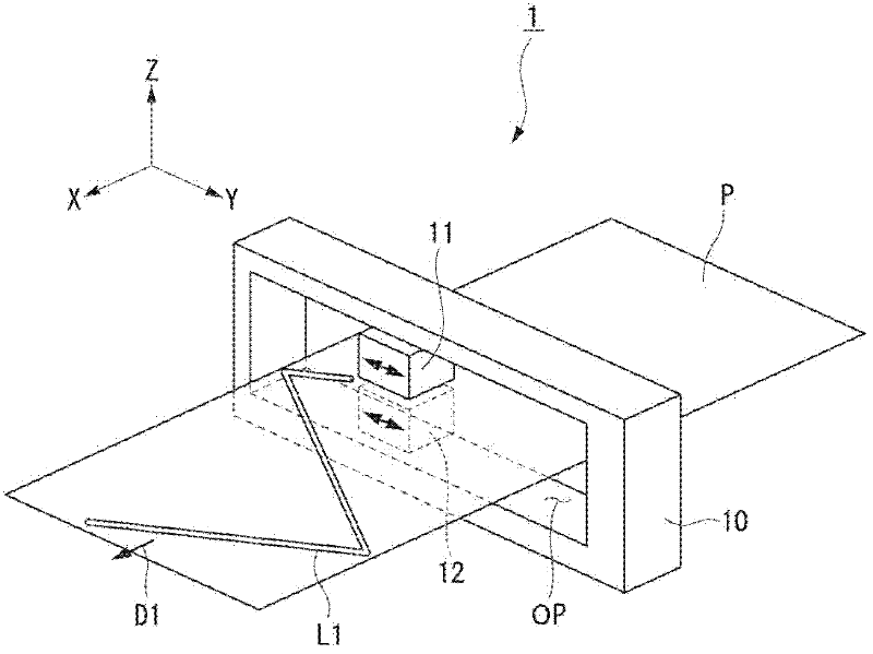
[0026] figure 1 It is a perspective view showing a schematic structure of a moisture meter a...


PUM


Abstract

An infrared analysis apparatus may include a first head and a second head. The first head may include a plurality of light sources each of which irradiates rays of infrared light having different wavelengths on a test object, and an optical element that is disposed between the plurality of light sources and the test object, the optical element making intensity distribution of the infrared light uniform. The second head may include a detector that detects the infrared light transmitted through the test object.

Description

technical field [0001] The present invention relates to an infrared analysis device for analyzing the characteristics of an inspection object using infrared light. [0002] This application claims priority based on Japanese Patent Application No. 2011-038246 for which it applied on February 24, 2011, and uses the content here. Background technique [0003] It is clear that patents, patent applications, patent publications, scientific literature, etc. are cited below, but the contents thereof are hereby incorporated herein in order to more fully illustrate the prior art of the present invention. [0004] Infrared analysis device, by irradiating infrared light on the inspection object, receiving the infrared light passing through the inspection object or the infrared light reflected and scattered by the inspection object, and calculating the transmission characteristics or reflection characteristics, so as to carry out the analysis of the inspection object. examine. This inf...

Claims


Application Information

Patent Timeline
Patent Type & Authority Applications(China)
IPC IPC(8): G01N21/35G01N21/3554
CPCG01N21/3554G01N21/3559G01N21/86G01N33/346G01N2201/0627G01N2201/0631
Inventor 市泽康史堀越久美子辻井敦角田重幸
Owner YOKOGAWA ELECTRIC CORP
Why Eureka
Try Eureka