Uterine spherical silicon rubber intrauterine device

An intrauterine device and spherical silicon technology, which is applied in the direction of female contraceptives, etc., can solve the problems of difficulty in achieving the ideal level of contraceptive effect, insufficient deployment of the IUD, and difficulty in reaching the set volume, etc., and achieves improved contraceptive effect and light weight. , the effect of simple structure

Inactive Publication Date: 2013-12-04
王磊光 +1
View PDF8 Cites 0 Cited by
  • Summary
  • Abstract
  • Description
  • Claims
  • Application Information

AI Technical Summary

Problems solved by technology

The IUDs mentioned above are all planar structures, which are prone to falling off and shifting
In addition, due to the limited space in the uterine cavity occupied by the planar structure of the existing IUD, it is difficult to cause aseptic inflammation in a large enough area of ​​the uterine cavity, so that the contraceptive effect is difficult to reach the ideal level
In addition, there are a few existing IUDs with a three-dimensional structure. After being placed in the body, the IUD is not fully expanded, and it is difficult to reach the set volume. Therefore, it cannot effectively contact the inner wall of the uterine cavity, and the contraceptive effect is not ideal.

Method used


Image

  • Uterine spherical silicon rubber intrauterine device
  • Uterine spherical silicon rubber intrauterine device
  • Uterine spherical silicon rubber intrauterine device

Examples


Embodiment Construction

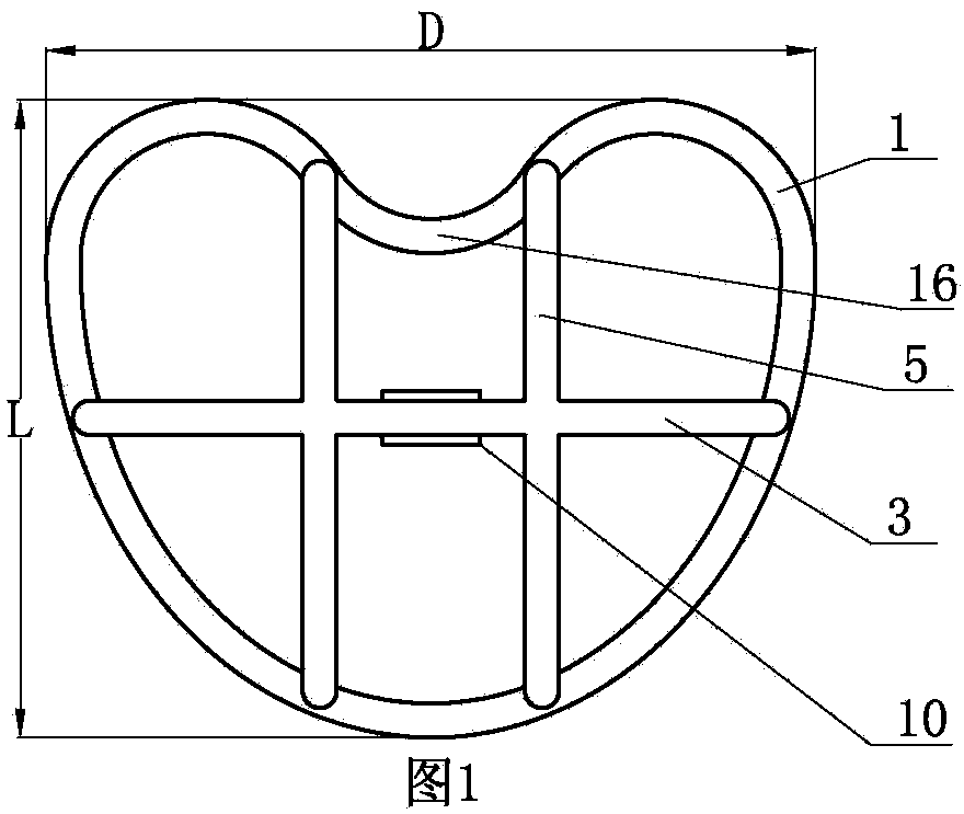
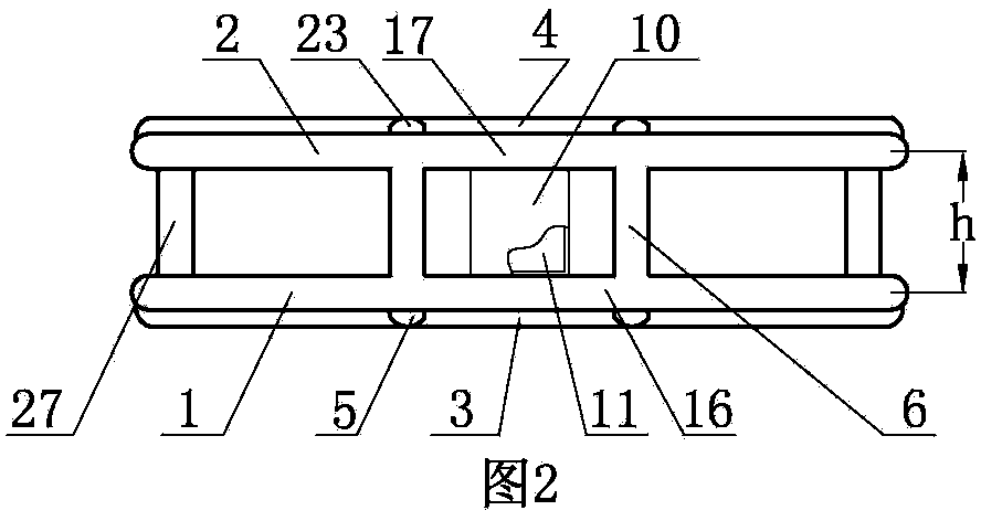
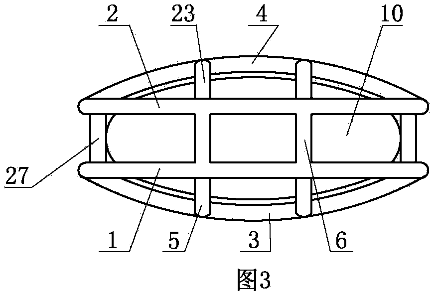
[0009] The uterine cavity spherical silicone rubber IUD of the present invention comprises a first ring body 1 and a second ring body 2, such as figure 1 As shown, both the first ring body 1 and the second ring body 2 are heart-shaped, which can facilitate the discharge of intrauterine fluid; the first ring body 1 and the second ring body 2 are connected by two side connecting ribs 27 and two upper ribs. The ribs 6 are connected, the two upper connecting ribs 6 are located on the top of the first ring body 1 and the second ring body 2, and the two side connecting ribs 27 are located at the bottom of the first ring body 1 and the second ring body 2, and are distributed left and right. The first ring body 1 and the second ring body 2 are connected by two side connecting ribs 27 and two upper connecting ribs 6 to form a three-dimensional spherical structure, so that the uterine cavity spherical silicone rubber IUD can be more fully inserted into the uterus. Occupying a space to a...


PUM

PropertyMeasurementUnit
Maximum widthaaaaaaaaaa
Maximum heightaaaaaaaaaa

Abstract

The invention discloses a uterine spherical silicon rubber intrauterine device which comprises two ring bodies connected through a lateral connection rib and an upper connection and provided with vertical ribs and transverse ribs. An air bag is installed between two transverse ribs, an expansion box is installed in the air bag, and two connection parts are arranged on the expansion box and penetrate through the air bag to be connected with the two transverse ribs. The expansion box comprises two casings, one end of a first casing is provided with a first connection part, the other end of the first casing is provided with two inserting heads, boss through holes and grooves are arranged on the inserting heads, elastic pieces are installed on the inserting heads, and positioning bosses are installed on the elastic pieces. A second casing is installed on the first casing and provided with two inserting holes, lateral holes are arranged on the lateral walls of the inserting holes, and a cavity and two through holes are arranged in the second casing. One end of the second casing is provided with a positioning block groove, a positioning block is installed in the positioning block groove, and a lifting connection board is installed in the cavity and provided with two wedge blocks and a connection rod which is fixedly connected with the positioning block.

Description

technical field [0001] The invention relates to a uterine cavity spherical silicone rubber intrauterine device. Background technique [0002] The IUDs currently used mainly contain metal single rings, gamma-shaped, T-shaped, M-shaped, U-shaped, etc., but the metal single ring is the most. The contraceptive devices mentioned above are all planar structures, which are prone to shedding and displacement. In addition, due to the limited space in the uterine cavity occupied by the planar structure of the existing IUD, it is difficult to cause aseptic inflammation in a large enough area of ​​the uterine cavity, thereby making it difficult to achieve an ideal contraceptive effect. In addition, there are few existing IUDs with three-dimensional structures. After being put into the body, the IUDs are not fully expanded and difficult to reach the set volume. Therefore, they cannot effectively contact the inner wall of the uterine cavity, and the contraceptive effect is not ideal. C...

Claims


Application Information

Patent Timeline
IPC IPC(8): A61F6/16
Inventor 王磊光邱毅
Owner 王磊光
Why Eureka
Try Eureka