
Unfolding and machining method for single-bent thin-walled parts

A technology of thin-walled parts and thin-walled parts, applied in the field of sheet metal forming, can solve the problems that the position and size of the milling grid are not very accurate, not suitable for product design requirements, and the wall thickness tolerance of parts cannot be guaranteed.

Inactive Publication Date: 2012-09-12
SHENYANG AIRCRAFT CORP
View PDF2 Cites 6 Cited by
  • Summary
  • Abstract
  • Description
  • Claims
  • Application Information

AI Technical Summary

Problems solved by technology

Its disadvantages are: in order to ensure the quality of the parts, the number of subsidence layers of the part chemical milling cannot be more than 5 times, otherwise the part wall thickness tolerance cannot be guaranteed, the position and size control of the chemical milling grid is not very accurate, the error is about 1mm, and the machining needs Dedicated large-scale machining equipment, etc.
However, a necessary condition of this solution is that the sag shape of the thin-walled part must be relatively large and simple, and the sag depth can be transformed into a single thin-walled part, and this necessary condition is obviously not suitable for the current increasingly complex product design requirements.

Method used


Image

  • Unfolding and machining method for single-bent thin-walled parts
  • Unfolding and machining method for single-bent thin-walled parts
  • Unfolding and machining method for single-bent thin-walled parts

Examples


Embodiment Construction

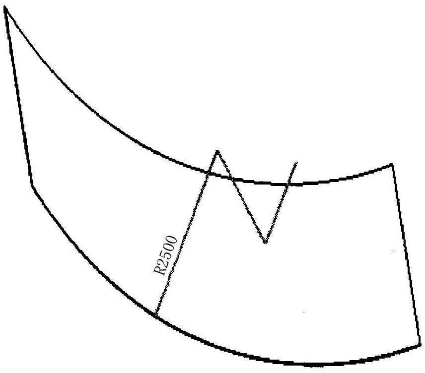
[0013] Such as figure 1 As shown, for an aluminum-lithium alloy 2198 thin plate with an outer dimension of 3200mm×2100mm×3.175mm, after the size of the part needs to be processed, the radius of curvature is required to be 1667.5mm. The unfolding machining method for this single-curved thin-walled part includes the following steps:

[0014] 1) Pre-rolling of thin-walled parts: the radius of rolling thin-walled parts is 1000mm larger than the final curvature radius of 1667.5mm, and the pre-rolling radius is 2500mm~2600mm;

[0015] 2) A large number of tests have proved that when the pre-rolling radius of the thin-walled part is greater than R1000mm, when the thin-walled part is unfolded and clamped, the force on the thin-walled part has no effect on the final weight of the thin-walled part, so the thin-walled part Unfold machining; unfold the thin-walled parts on the vacuum platform of the CNC equipment and clamp them to keep the processing surface level of the thin-walled parts...


PUM

PropertyMeasurementUnit
Radius of curvatureaaaaaaaaaa

Abstract

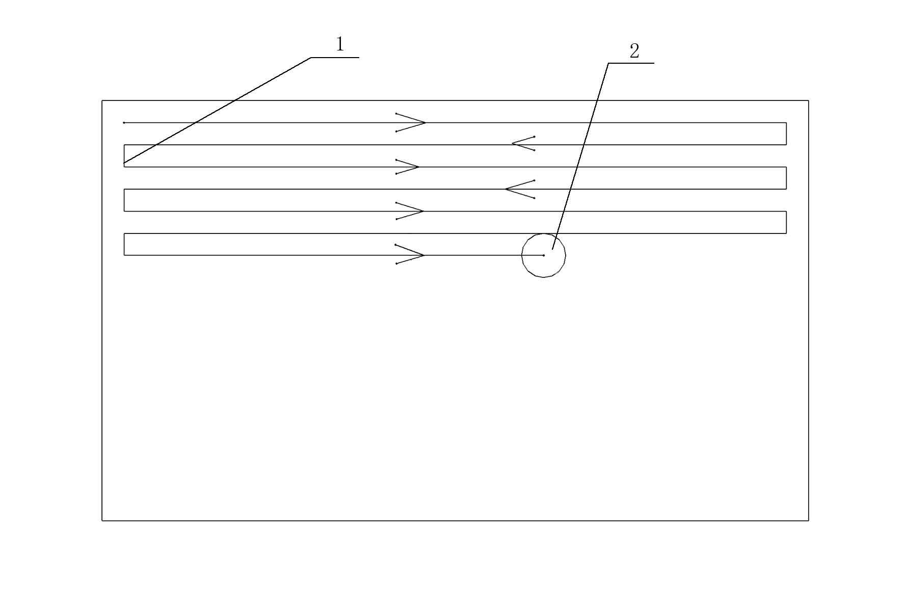
The invention relates to an unfolding and machining method for single-bent thin-walled parts, which is applicable to thin-walled parts with a curvature radius of more than 1000 mm. The method is characterized by comprising the following steps of: 1) carrying out pre-roll bending on thin-walled parts, wherein the rolled radius of each thin-walled part is 1000 mm larger than the final curvature radius thereof; 2) carrying out unfolding and machining on the thin-walled parts, namely, unfolding the thin-walled parts on a vacuum platform of a numerical control device to be clamped, keeping the machined surfaces of the thin-walled parts horizontal, and machining the thin-walled parts through selecting a high-speed milling numerical control machining mode, wherein the machining path is a longitudinal serpentine milling path; and 3) discharging the parts from the vacuum platform, and placing the parts in a natural state, so that the final technical requirement can be satisfied. The method is not only simple, but also can save a lot of production cost on the premise of ensuring the quality and machining cycle of the parts.

Description

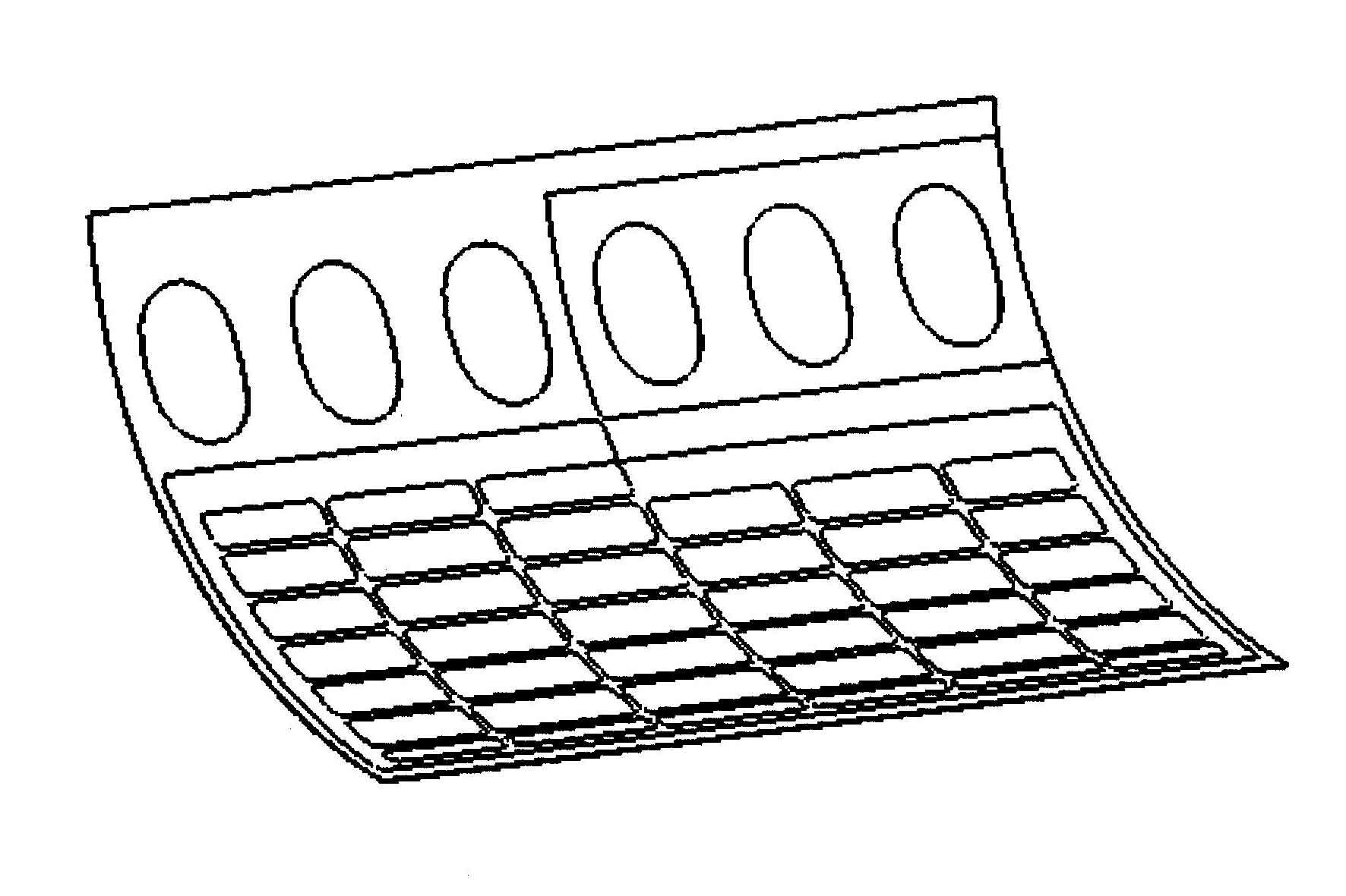
technical field [0001] The invention relates to an unfolding machining method for a single curved thin-walled part, which belongs to the field of sheet metal forming. Background technique [0002] The existing traditional processing schemes for single curved thin-walled parts are divided into two ways. One way is to chemically mill the thickness and sink of the part after the sheet metal is formed, and then add the inner shape on the milling clamp. At present, most of the thin-walled parts adopt this processing scheme. The feature of this scheme is that the processing cycle is longer, the quality is relatively stable, and the processing cost is higher. Its disadvantages are: in order to ensure the quality of the parts, the number of subsidence layers of the part chemical milling cannot be more than 5 times, otherwise the part wall thickness tolerance cannot be guaranteed, the position and size control of the chemical milling grid is not very accurate, the error is about 1m...

Claims


Application Information

Patent Timeline
IPC IPC(8): B23P13/02
Inventor 王建华王君宇张跃兴
Owner SHENYANG AIRCRAFT CORP
Learn More