Automatic discharging die-cutting machine

An automatic cutting and die-cutting machine technology, applied in metal processing and other directions, can solve the problems of low positioning efficiency and stacking accuracy, improper cooperation between two people, and high labor costs, saving labor, improving production efficiency, and high automation.

Inactive Publication Date: 2012-09-12
魏祥国
View PDF10 Cites 4 Cited by
  • Summary
  • Abstract
  • Description
  • Claims
  • Application Information

AI Technical Summary

Problems solved by technology

Because two people need to stand in front of the die-cutting table, this invention has the following disadvantages: ① two people operate, and the labor cost is high; ② improper cooperation between two people is likely to cause safety accidents
In addition, the blanking staff manually placed the die-cut plates in the finished product area, and the positioning efficiency and stacking accuracy were relatively low.

Method used


Image

  • Automatic discharging die-cutting machine
  • Automatic discharging die-cutting machine
  • Automatic discharging die-cutting machine

Examples


Embodiment Construction

[0024] The present invention will be further described below in conjunction with the accompanying drawings and specific embodiments.

[0025] The invention includes a frame, a motor assembly, a die-cutting platen, a die-cutting assembly and a blanking assembly.

[0026] For the convenience of description and reference (but not limited thereto), the sliding direction of the die-cutting assembly of the present invention is defined as "left" and "right", and the remaining two sides are defined as "near end" and "far end", wherein the approaching operation The operator's end is called "near end", and the end away from the operator is called "far end". The side of the blanking assembly of the present invention facing the operator is referred to as "front", and the side away from the operator is referred to as "back".

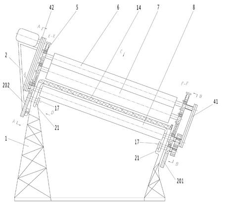
[0027] Such as figure 1 As shown, the frame 1 is a similar cuboid frame, and the die-cutting table 14 is fixedly installed on the frame 1 . A horizontal guide rai...


PUM


Abstract

The invention discloses an automatic discharging die-cutting machine and belongs to the field of machinery. The automatic discharging die-cutting machine comprises a frame, a motor assembly, a die-cutting table plate and a die-cutting assembly and is characterized by further comprising a discharging assembly. The discharging assembly comprises a discharging support, a discharging arm, a suction device, a discharging motor and a transmission device. The discharging support comprises a slide way and a rocker which are mounted on a support body, and the slide way has a certain radian. The discharging arm comprises a sucker holder and a discharging arm body, and the suction device comprises a vacuum pump, a position switch, an electromagnetic reversing valve, a sucker, an air storage device and a pipeline. The discharging motor is connected with the transmission device and a travelling end of the discharging arm body sequentially, a die-cutting limiting switch and a discharging trigger switch are arranged on the frame, the die-cutting limiting switch is in circuit connection with a motor, and the discharging trigger switch is in circuit connection with the discharging motor. Compared with the prior art, the automatic discharging die-cutting machine has the advantages that automatic discharging can be realized, labor intensity is relieved for workers, and labor is saved.

Description

technical field [0001] The invention relates to a die-cutting machine, in particular to a die-cutting machine suitable for small batches and individualized post-press die-cutting. Background technique [0002] Die-cutting machine is mainly used for die-cutting (full cut, half-cut), indentation and bronzing of some non-metallic materials, self-adhesive, double-sided tape, electronics, mobile phone rubber pads, etc. important equipment. The working principle of the die-cutting machine is to use the template carved by steel knife, metal mold, steel wire or steel plate, and apply a certain pressure through the embossing plate to cut the printed matter or cardboard into a certain shape. The main parts of the die-cutting machine are the die-cutting platen and the press-cutting mechanism. The processed sheet is between the two, and the finishing technology of die-cutting is completed under the action of pressure. [0003] According to the different embossing forms, the die-cuttin...

Claims


Application Information

Patent Timeline
Patent Type & Authority Applications(China)
IPC IPC(8): B26F1/42B26D7/32
Inventor 魏祥国张作状
Owner 魏祥国
Why Eureka
Try Eureka