Protected seam bottom plate upward comb-shaped drilled hole gas extraction method
A protected layer and gas drainage technology, applied in the direction of gas discharge, earth drilling, mining equipment, etc., can solve the problems of increasing the cost of extraction, affecting the mining efficiency and cycle, and the large amount of drilling engineering, so as to improve the gas consumption. Drainage efficiency, shorten the mining cycle, reduce the effect of construction costs
- Summary
- Abstract
- Description
- Claims
- Application Information
AI Technical Summary
Problems solved by technology
Method used
Image


Examples
Embodiment Construction
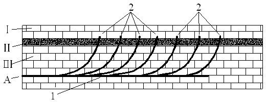
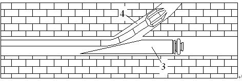
[0017] Such as figure 1 As shown, in the protected layer floor comb-shaped drilling gas drainage method of the present invention, firstly, a drilling field A is arranged in the protected layer bottom plate III, and a main hole 1 is first drilled in the drilling field A along the direction of the working face, and the main hole 1 The vertical distance between the horizontal position and the protected layer II is 15-25m; stop drilling after the main hole 1 is drilled 15m, ream the main hole 1, install the sealing pipe in the reaming hole, install the sealing pipe The length of the main hole 1 is 8 ~ 15m; install the blowout preventer and the gas-water separator at the orifice; continue to drill the main hole 1 along the direction of the working face until the main hole 1 reaches the set depth; Insert the packing whipstock 3 to the innermost end, then set the position of the first forced deflection point from the inside to the outside, and use the bottom motor 4 with a small diam...
PUM
| Property | Measurement | Unit |
|---|---|---|
| Length | aaaaa | aaaaa |
Abstract
Description
Claims
Application Information
PatSnap Eureka turns technology decisions into work you can execute. Powered by our Innovation Knowledge Graph, it runs expert workflows across engineering, life sciences, materials and intellectual property. Get your review-ready output in minutes.


