
LED fluorescent lamp tube and method for manufacturing same

A technology of LED fluorescent lamp and LED light source, which is applied in the direction of light source, electric light source, light source fixation, etc., can solve the problems of glass tube being fragile, failing to reach the lighting angle, and high cost, and achieve the effect of reducing production cost and increasing the lighting angle

Inactive Publication Date: 2012-09-12
SUNSUN LIGHTING CHINA
View PDF8 Cites 14 Cited by
  • Summary
  • Abstract
  • Description
  • Claims
  • Application Information

AI Technical Summary

Problems solved by technology

[0003] The overall structure of existing LED fluorescent lamps can be divided into two categories: the first category is a PC lampshade plus an aluminum radiator, an aluminum substrate is fixed on a long aluminum radiator, and then several LED light sources are fixed on the aluminum substrate, and then Fix the PC lampshade on the strip-shaped aluminum radiator, and then connect the circuit. The advantage of this type of LED fluorescent lamp is that the technology is mature and the threshold is low; however, the disadvantages are also obvious: the main cost is high, and because the light source is generally located The diameter of the tube makes the spatial luminous angle of the tube smaller, which cannot reach the luminous angle of the traditional fluorescent tube.
The second type is a circuit board plus a glass tube. Fix a number of LED light sources on the circuit board, and then apply some glue on the back of the circuit board to stick the circuit board in the glass tube, and then connect the circuit. Although this type of LED fluorescent tube is not It will be applied to aluminum radiators, which reduces the cost, but the disadvantages are also obvious: the glass tube is fragile, especially when the glass tube is broken, the LED light source is directly exposed, which poses a safety hazard, and the light emitted by the LED light source is also glaring. , is not conducive to human vision

Method used


Image

  • LED fluorescent lamp tube and method for manufacturing same
  • LED fluorescent lamp tube and method for manufacturing same
  • LED fluorescent lamp tube and method for manufacturing same

Examples


Embodiment Construction

[0023] Below in conjunction with accompanying drawing, the technical scheme of invention is described in detail:

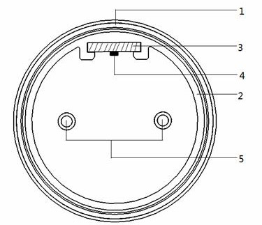
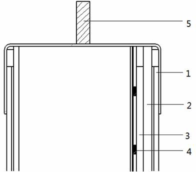
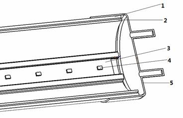
[0024] like figure 1 , 2 , The LED fluorescent tube shown in 3 and 4 includes a glass tube 1, a plastic tube 2, a circuit board 3, an LED light source 4, and two lamp caps 5, and the plastic tube 2, the circuit board 3, and the LED light source 4 are all packaged in the glass tube 1 Inside, two lamp caps 5 are installed at both ends of the glass tube 1 respectively. The LED light source 4 is fixed on the circuit board 3, the plastic pipe 2 is provided with a card slot, the circuit board 3 is fixed in the plastic tube 2 through the card slot, and the circuit board 3 divides the cylindrical plastic tube 2 into two arc-shaped cross-sections cavity.

[0025] The position of the circuit board 3 in the plastic tube 2 can be adjusted so that the ratio of the cross-sectional areas of the two cavities is 1:0.01-1:1, and the area ratio of the two cross-sectional areas is...


PUM


Abstract

The invention discloses an LED fluorescent lamp tube, and belongs to the technical field of illumination of semiconductors. The LED fluorescent lamp tube comprises a glass tube, a plastic tube, a circuit board, an LED light source and two lamp holders, the plastic tube, the circuit board and the LED light source are packaged in the glass tube, the two lamp holders are respectively mounted at two ends of the glass tube, the LED light source is fixed onto the circuit board, a clamp groove is arranged in the plastic tube, the circuit board is fixed into the plastic tube by the aid of the clamp groove and divides the cylindrical plastic tube into two cavities, and the cross sections of each cavity is arc-shaped. The invention further discloses a method for manufacturing the LED fluorescent lamp tube. The position of the LED light source is adjusted by means of adjusting the position of the circuit board in the cavities of the plastic tube, accordingly, the LED light source is prevented from being positioned at a circumferential position of the lamp tube, and the luminescence angle of the lamp tube is increased. In addition, the circuit board is selectively made of environment-friendly materials such as a ceramic substrate or an epoxy glass laminated sheet, heat generated by the LED light source is dissipated in an energy-saving and environment-friendly manner, and production cost is reduced.

Description

technical field [0001] The invention discloses an LED fluorescent lamp tube and a manufacturing method thereof, belonging to the technical field of semiconductor lighting. Background technique [0002] Semiconductor lighting is developing rapidly due to its advantages of energy saving, environmental protection, and fast response. In the field of indoor lighting, LED fluorescent tubes are challenging the traditional fluorescent tubes due to their energy-saving advantages and are constantly replacing the latter. [0003] The overall structure of existing LED fluorescent lamps can be divided into two categories: the first category is a PC lampshade plus an aluminum radiator, an aluminum substrate is fixed on a long aluminum radiator, and then several LED light sources are fixed on the aluminum substrate, and then Fix the PC lampshade on the strip-shaped aluminum radiator, and then connect the circuit. The advantage of this type of LED fluorescent lamp is that the technology is...

Claims


Application Information

Patent Timeline
Patent Type & Authority Applications(China)
IPC IPC(8): F21S2/00F21V19/02F21V29/00F21Y101/02F21K9/27F21K9/66F21V29/503F21V29/85F21Y115/10
Inventor 孙建宁江新光李荣花冼钰伦
Owner SUNSUN LIGHTING CHINA
Learn More