Eureka AIR delivers breakthrough ideas for toughest innovation challenges, trusted by R&D personnel around the world.

Heat exchanger air inlet buffer structure

A technology of buffer structure and air inlet, which is applied in the direction of heat exchanger shell, heat exchange equipment, lighting and heating equipment, etc., can solve the problem of loose expansion joints between heat exchange tubes and tube sheets, economic losses in maintenance and replacement, and damage to heat exchange. Condition and other problems, to achieve the effect of reducing destructiveness, easy production, and obvious depressurization

Inactive Publication Date: 2012-09-12
泰州市远望换热设备有限公司
View PDF6 Cites 1 Cited by
  • Summary
  • Abstract
  • Description
  • Claims
  • Application Information

AI Technical Summary

Problems solved by technology

However, when the pressure of the compressed air used for heat replacement is high, it will inevitably hit the built-in heat exchange tube head-on. The strong wind blowing through it will easily cause deformation of the heat exchange tube and loosening of the expansion joint between the heat exchange tube and the tube sheet, and even cause fracture and damage.
Once the heat exchange elements in the heat exchanger are damaged, the heat replacement conditions will be destroyed, and repair and replacement will cause economic losses

Method used


Image

  • Heat exchanger air inlet buffer structure
  • Heat exchanger air inlet buffer structure
  • Heat exchanger air inlet buffer structure

Examples


Embodiment Construction

[0014] The present invention will be further described below according to the accompanying drawings and in conjunction with the embodiments.

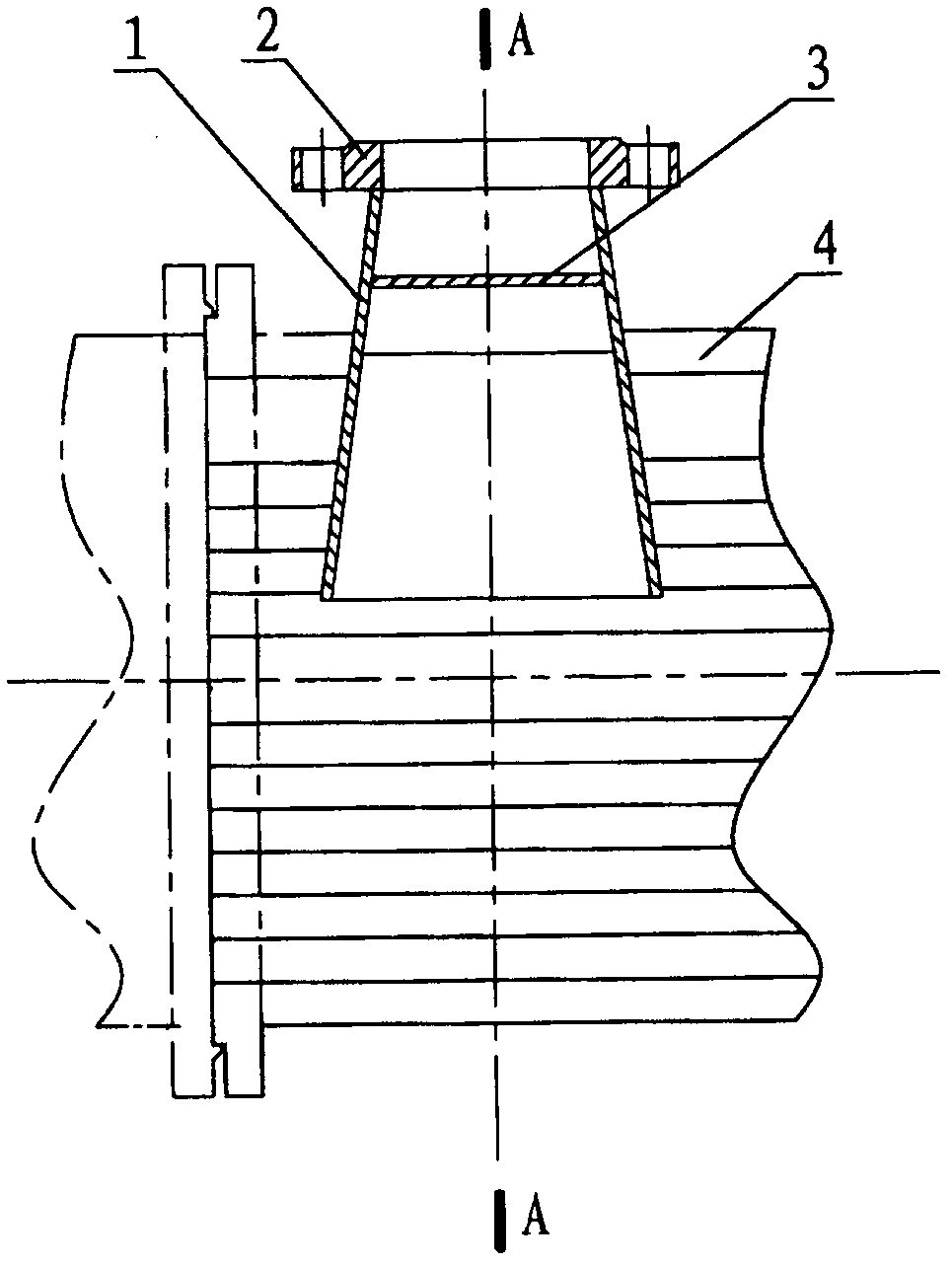
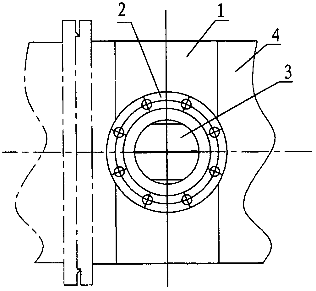
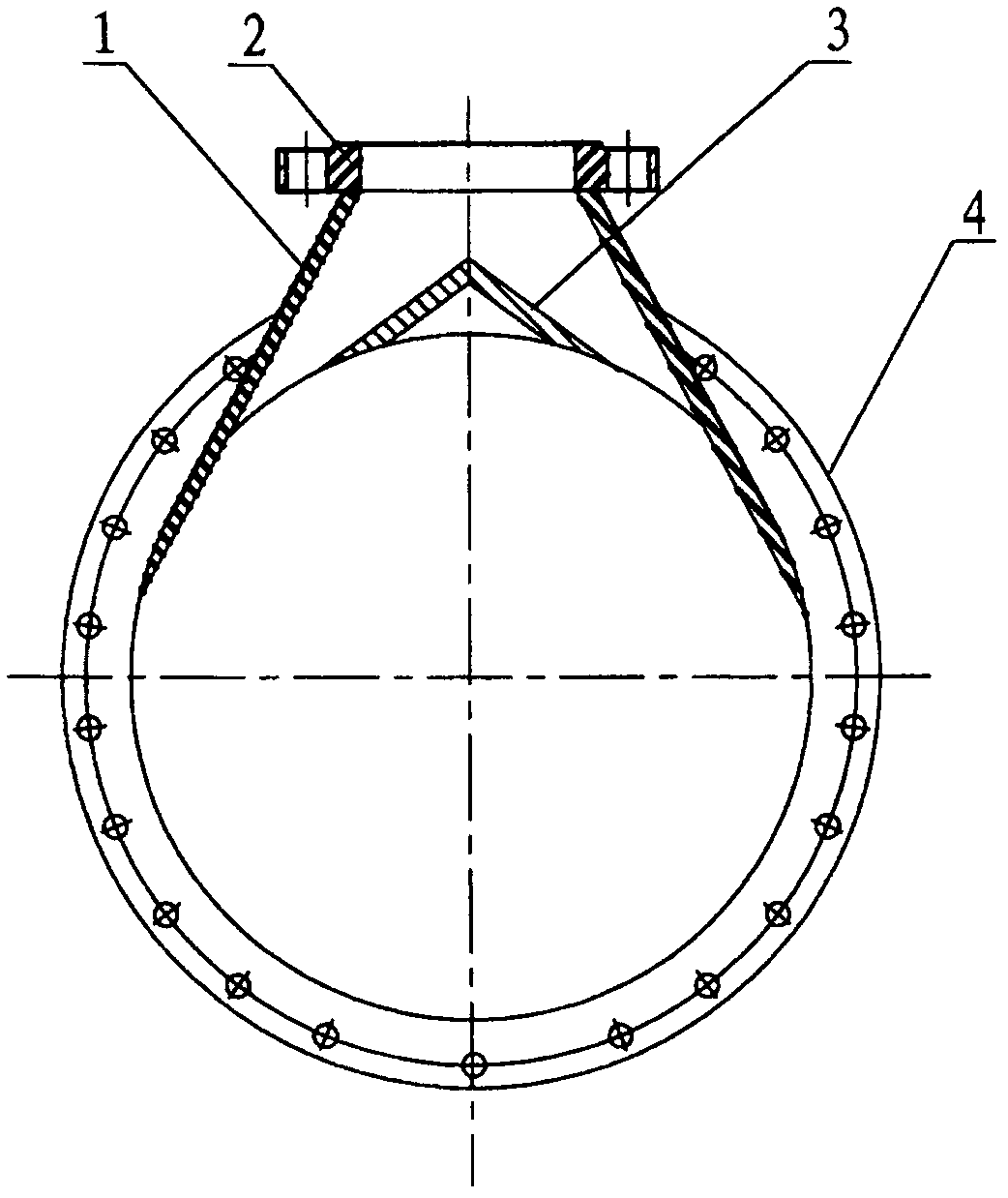
[0015] figure 1 The air inlet buffer structure of the heat exchanger shown includes an air inlet and a deflector 3 fixedly connected to the side cylinder wall of the displacement section 4 . The air inlet is a rectangular tapered tube 1 with a large inside and a small outside. The flange 2 connected to the outside is arranged at the small end of the rectangular tapered tube 1 , and the other end is in sealing connection with the cylinder wall of the replacement section 4 . image 3 with figure 2 The deflector 3 shown is a rectangular plate bent in the center to form a corner plate. In this embodiment, it is bent into a 120° angle plate with the outwardly convex bending seam facing outward. The deflector 3 constitutes a frontal barrier and plays a buffering role. In addition, two diffused passages are formed between both sides of the...


PUM


Abstract

The invention discloses a heat exchanger air inlet buffer structure which comprises an air inlet and a flow guide plate on the lateral cylinder wall of a replacement section, wherein the air inlet is a rectangular conical tube which is large in inner part and is small in outer part; a flange is installed at the small end of the rectangular conical tube, and the other end of the rectangular conical tube is connected with the cylinder wall of the replacement section in a seal mode; the flow guide plate is a middle-placed bending angle plate; an outer protruding bending seam is outward and is coaxially connected with the replacement section in a seal mode; the middle-placed flow guide plate forms a frontage protective screen which plays a role of buffer; and additionally, two diffusion-shaped channels are formed between two sides of the flow guide plate and the rectangular conical tube, and the diffusion-shaped channels and the cylinder wall of the replacement section transit naturally so as to form a speed-reduction and pressure-reduction structure. According to the invention, through the additional arrangement of the buffer structure at the air inlet and the change of the diffusion-shaped channels at two sides, the frontage of a heat exchange tube is prevented from being impacted by air flows, and the heat exchange elements are prevented from being damaged.

Description

technical field [0001] The invention relates to an improved structure of a heat exchanger, in particular, the invention relates to an improved structure of an air inlet of a heat exchanger. Background technique [0002] Heat exchangers are traditional industrial products and are widely used in manufacturing. The air inlet of the heat exchanger in the prior art is a straight-through pipe, which has a simple structure, is easy to manufacture, and can meet heat replacement conditions. However, when the pressure of the compressed air used for heat replacement is high, it will inevitably hit the built-in heat exchange tube head-on, and the strong wind blowing through it will easily cause deformation of the heat exchange tube and loosening of the expansion joint between the heat exchange tube and the tube sheet, and even cause fracture and damage. Once the heat exchange elements in the heat exchanger are damaged, the heat replacement conditions will be destroyed, and repair and r...

Claims


Application Information

Patent Timeline
Patent Type & Authority Applications(China)
IPC IPC(8): F28F9/00
Inventor 戴燕左小东曹润周留明陆俊霞
Owner 泰州市远望换热设备有限公司
Why Eureka
Eureka Blog
Learn More