
Pile foundation control blasting excavation method of integral-plate rocky area

A technology for controlling blasting and rock areas, applied in blasting and other directions, can solve problems such as rock cracking around the pile foundation and at the bottom of the pile, reduce rock clamping force, and weaken strong vibration of blasting, so as to reduce rock clamping force and weaken blasting The effect of strong vibration and quality assurance

Active Publication Date: 2014-08-06
湖南省第五工程有限公司
View PDF4 Cites 0 Cited by
  • Summary
  • Abstract
  • Description
  • Claims
  • Application Information

AI Technical Summary

Problems solved by technology

[0004] The present invention aims at the slow excavation and pile diameter difficult to control in the prior art where there are pile foundations directly blasting and excavating in the whole rock area, and it is easy to cause rock cracks around the pile foundation and at the bottom of the pile, which affects the excavation of adjacent piles, Due to the technical problems of perforation between piles and shock cracking of the bearing layer at the bottom of the pile, a new pile foundation controlled blasting excavation method for the entire rock area is proposed, which can reduce the rock clamping force, weaken the strong vibration of blasting, and The rock around the pile foundation and the rock of the bearing layer at the bottom of the pile will not cause shock cracking and fragmentation. It can effectively ensure the safety of excavation of adjacent piles in the pile foundation dense area, and the quality of the bearing layer at the bottom of the pile is also effectively guaranteed. After blasting, the pile The hole section is regular and the block degree is uniform

Method used


Image

  • Pile foundation control blasting excavation method of integral-plate rocky area
  • Pile foundation control blasting excavation method of integral-plate rocky area
  • Pile foundation control blasting excavation method of integral-plate rocky area

Examples


Embodiment Construction

[0018] The invention provides a pile foundation controlled blasting excavation method for a whole slab of rock area, comprising the following steps:

[0019] S1. Excavate and level the entire rock area, and locate the pile foundation;

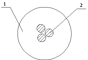
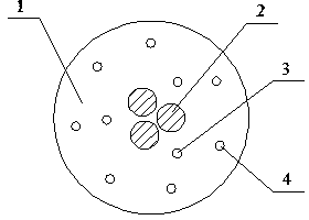
[0020] S2. Drill several pile core holes 2 in the center of the positioned pile foundation to form a pile core hollow area;

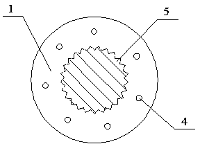
[0021] S3. Drill at least two circles of holes evenly arranged in the outer ring of the hollow area of ​​the pile core, and obtain several circles of blastholes that are evenly arranged in the circumferential direction and arranged in an intersecting arrangement, including the inner ring blasthole 3 of the innermost ring and the holes evenly distributed in the inner ring. A number of outer ring blastholes around the blasthole;

[0022] S4. Load rock emulsion explosives and millisecond delay detonators into all blastholes, and the detonation time of the detonators located in the outer blastholes in every two adjacent bla...


PUM


Abstract

The invention provides a pile foundation control blasting excavation method of an integral-plate rocky area, wherein the method comprises the following steps: S1. excavating and flattening a field, and positioning a pile foundation; S2. drilling a pile center hole at the central part of the pile foundation; S3. forming a shot hole at the inner annular direction of the pile foundation; S4. charging in the shot hole, and blasting; and S5 clearing slag in the pile hole, and protecting a wall, and carrying out control blasting excavation on the next stage of pile foundation until the pile foundation is finished. The method provided by the invention can lower the clipping force of rocks, weaken the blasting strong vibration, and meanwhile reduce the blasting gunpowder quantity, and the shattering and crushing phenomenon can not be caused to the rocks at the periphery of the pile foundation and rocks at the clipping force layer at the pile foundation; the excavation safety of the adjacent pile at the area with great density can be ensured effectively, the quality of the rocks at the clipping force layer at the bottom of the pile is ensured effectively, the cross section of the pile hole after blasting is even, and the block degree is uniform.

Description

technical field [0001] The invention relates to the field of building construction, in particular to a method for controlled blasting and excavation of a pile foundation in a whole slab rock area. Background technique [0002] In recent years, pile foundation engineering has been widely used in urban high-rise buildings, and according to the different geological and hydrological conditions and geotechnical properties, there are also various ways of forming holes in pile foundations, such as artificial digging piles, punching piles, bored piles, Rotary excavation piles, etc., but on the basis of considering the technical and economic costs, artificial excavation piles are still used in some areas in China. Manual excavation piles are often limited by geological conditions, among which blasting and excavation of artificial excavation piles in rocky areas is one of the difficulties in construction. [0003] In the traditional rock blasting excavation in the pile foundation, bl...

Claims


Application Information

Patent Timeline
Patent Type & Authority Patents(China)
IPC IPC(8): F42D1/00F42D1/08F42D3/04F42D1/18
Inventor 黄孝芳熊用机王文革刘育奇龚学斌龙新乐张晚生龙兴颜昌明谭智谋陈宇刘福云冯浩
Owner 湖南省第五工程有限公司
Learn More