Visualized workflow engine system

A workflow engine and workflow technology, applied in data processing applications, resources, computing, etc., can solve problems such as high coupling between business processes and technical means, difficult maintenance, and difficult page modification or maintenance at the same time

Inactive Publication Date: 2012-09-12
GUANGDONG YOUMAI INFORMATION COMM TECH
View PDF6 Cites 48 Cited by
  • Summary
  • Abstract
  • Description
  • Claims
  • Application Information

AI Technical Summary

Problems solved by technology

[0003] In the traditional electronic workflow solution, the coupled method is usually adopted, that is, according to the actual business process, it is implemented with specific IT technology. However, the business process and technology of the electronic workflow application system realized in this way The means are highly coupled, requiring developers not only to have deep technical knowledge, but also to be familiar with business processes
Moreover, enterprises often have many business processes belonging to different application systems. If each application system implements such a workflow application system, there will inevitably be problems such as high cost, long cycle, and difficult maintenance. In addition, such a workflow The application system is often implemented according to the initial business process, so if the subsequent business process changes, the workflow application system may also face major adjustments
[0004] However, the management of tasks is ever-changing with different business needs, daily office automation can no longer cover everything, and the demand for data transmission and management is becoming increasingly urgent
In the traditional way, interface development technicians need to individually design the

Method used


Image

  • Visualized workflow engine system
  • Visualized workflow engine system
  • Visualized workflow engine system

Examples


Embodiment Construction

[0025] The present invention will be further described in detail below with reference to the accompanying drawings and in combination with specific embodiments.

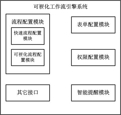
[0026] The invention provides a visual workflow engine, which is an innovative workflow management system, based on the B / S architecture of .NET, and can quickly define and implement workflows. Such as figure 1 As shown, the visual workflow engine system includes:

[0027] The process configuration module is used to configure the required business processes;

[0028] The form configuration module is used to configure the forms required by each business process;

[0029] The authority configuration module is used to configure the corresponding operation authority for each business process;

[0030] The intelligent reminder module is used to send reminder reports to roles in each business process.

[0031] The process configuration module includes:

[0032] The rapid process configuration module is used to quickly...


PUM


Abstract

The invention relates to a visualized workflow engine system, which comprises a flow configuration module, a form configuration module, a permission configuration module, an intelligent reminding module and a plurality of functional interfaces, wherein the flow configuration module is used for a needed business flow; the form configuration module is used for configuring a form needed by each business flow; the permission configuration module is used for configuring a corresponding operation permission respectively for each business flow; the intelligent reminding module is used for transmitting a reminding report to a role in each business flow; and the functional interfaces are used for other non-flow systems to call the visualized workflow engine system. Due to the adoption of the visualized workflow engine system, the flow can be defined by real business personnel in a hauling way according to the business requirement, the attribute and the permission of a movable node are edited, and thus the business flow can be adjusted and configured in time on the background only according to new requirement change for the changing of the flow requirement.

Description

technical field [0001] The invention relates to the field of workflow automation management, in particular to a visual workflow engine system. Background technique [0002] The concept of workflow originated in the fields of production organization and office automation, and its purpose is to decompose work into well-defined tasks and roles, perform these tasks according to certain procedures and rules, and monitor them. According to the definition of WfMC (Workflow Management Coalition, the International Workflow Management Alliance), workflow is an automatic business process, which is manifested by participants taking actions on files, information and tasks according to regulations, and allowing them to be carried out among participants. Delivery, to help enterprises standardize the management of processes, shorten process operation time, quickly respond to market customer needs, meet flexible control flow needs, effectively monitor work progress, strengthen internal infor...

Claims


Application Information

Patent Timeline
IPC IPC(8): G06Q10/06
Inventor 陈强
Owner GUANGDONG YOUMAI INFORMATION COMM TECH
Why Eureka
Try Eureka