

Active noise attenuation system and sound absorption method on basis of minimum quadratic sum of reflecting acoustic pressure
A minimal and active technology, applied in the direction of sounding equipment, instruments, etc., can solve the problems of not being able to manufacture electronic control systems and not developing, and achieve the effects of light weight, direct control and small size
- Summary
- Abstract
- Description
- Claims
- Application Information
AI Technical Summary
Problems solved by technology
Method used
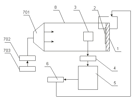
Image

Examples
Embodiment 1
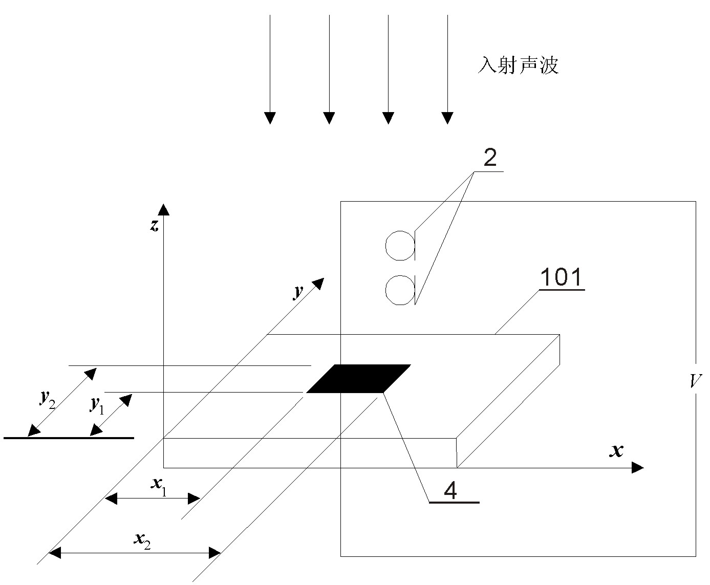
[0057] like figure 2 , based on the minimum square sum of the reflected sound pressure of a single piezoelectric ceramic wafer. Since the piezoelectric ceramic wafer is relatively thin, the elongation caused by the applied voltage is located in the direction perpendicular to the polarization direction. For the applied voltage ,strain for:
[0058] (7)
[0059] in, is the thickness of the piezoelectric ceramic wafer, is the strain constant of the piezoelectric ceramic wafer. like figure 2 As shown, the piezoelectric ceramic chip is pasted on the simply supported plate, and the bidirectional longitudinal force generated will be applied on the surface of the simply supported plate, and a moment will be generated on the simply supported plate. This moment is:
[0060] (8)
[0061] (9)
[0062] (10)
[0063] (11)...
Embodiment 2
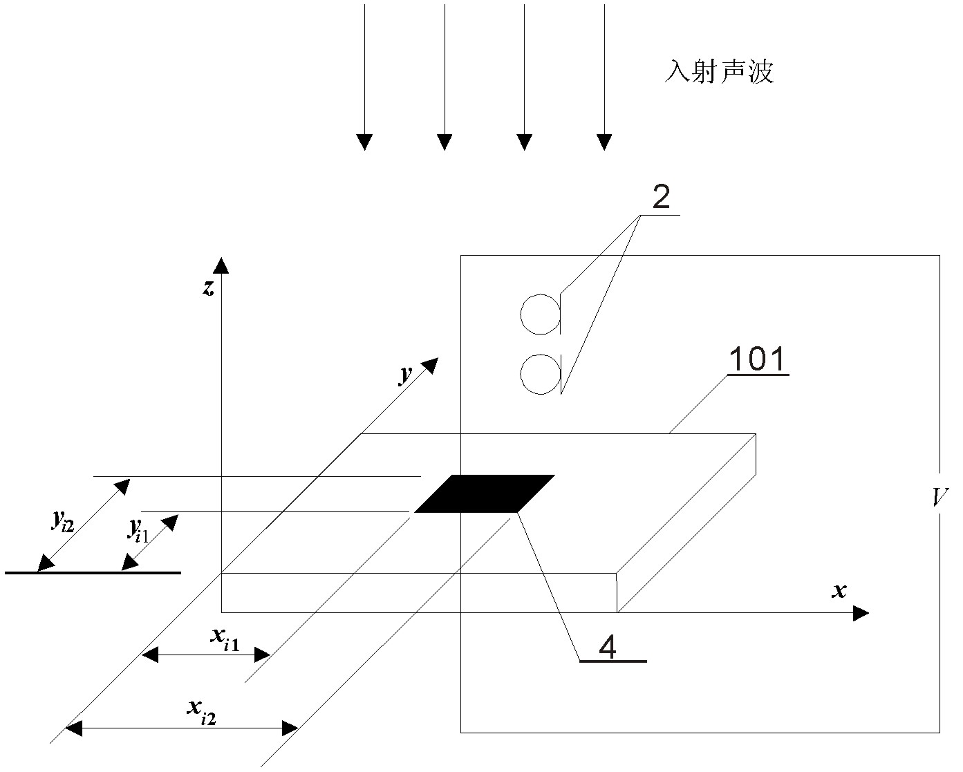
[0117] The sound absorption layout based on the minimum square sum of reflection sound pressure of multiple piezoelectric ceramic wafers is as follows: image 3 Shown:
[0118] For applied voltage , No. Piezoelectric Ceramic Chip Strain for:
[0119] (36)
[0120] in, for the first The thickness of the piezoceramic wafer, is the strain constant of the piezoelectric ceramic wafer. image 3 The piezoelectric ceramic chip is pasted on the simply supported plate, and the bidirectional longitudinal force generated will be applied on the surface of the simply supported plate, and a moment will be generated on the simply supported plate. This moment is:
[0121] (37)
[0122] (38)
[0123] According to formula (37), the first The longitudinal moment of the piezoelectric ceramic chip added to the surface of the simply supported plate, the equation of motion of the simply supported plate...
PUM
| Property | Measurement | Unit |
|---|---|---|
| Density | aaaaa | aaaaa |
| Thickness | aaaaa | aaaaa |
| Elastic modulus | aaaaa | aaaaa |
Abstract
Description
Claims
Application Information