
Feedback type laser energy wireless transmission device

A technology of laser energy and wireless transmission, applied in circuit devices, light radiation generators, electrical components, etc., can solve problems such as low safety, increased energy consumption, damage to personnel or equipment, etc., to achieve good safety and high efficiency Effect

Inactive Publication Date: 2012-09-12
TSINGHUA UNIV
View PDF5 Cites 19 Cited by
  • Summary
  • Abstract
  • Description
  • Claims
  • Application Information

AI Technical Summary

Problems solved by technology

[0004] This energy transmission mode requires real-time monitoring of the laser intensity at the receiving end, and keeping the communication between the transmitting end and the receiving end unimpeded. Once there is an alignment deviation between the transmitting end and the receiving end, the receiving end must detect it in time and immediately notify the transmitting end to stop energy transmission, otherwise it will be extremely dangerous. It is easy to cause damage to nearby personnel or equipment, and the safety is not high
In space, each spacecraft moves fast, long-term precise alignment is very difficult, the laser intensity at the receiving end changes rapidly, real-time monitoring is difficult, and maintaining communication increases additional energy consumption, the practical applicability is not strong

Method used


Image

  • Feedback type laser energy wireless transmission device
  • Feedback type laser energy wireless transmission device
  • Feedback type laser energy wireless transmission device

Examples


Embodiment 1

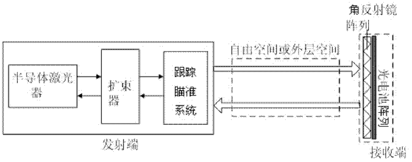
[0022] Embodiment 1: as figure 1 As shown, the feedback type laser energy wireless transmission device of the present invention includes a transmitting component at the transmitting end and a receiving component at the receiving end, the transmitting component includes a semiconductor laser and a beam expander, and the receiving component includes a photocell array. The transmitting assembly also includes a tracking and aiming system for tracking and aiming at the receiving end, and the receiving assembly also includes a corner reflector array arranged in front of the photocell array, which is used to reflect back a part of the laser beam from the emitting assembly to provide positive light for the semiconductor laser. Feedback, so that another part of the laser beam is transmitted to the photocell array. The laser beam is converted into electrical energy storage through a photocell array to realize wireless transmission of energy. The transmitter and receiver are separated b...

Embodiment 2

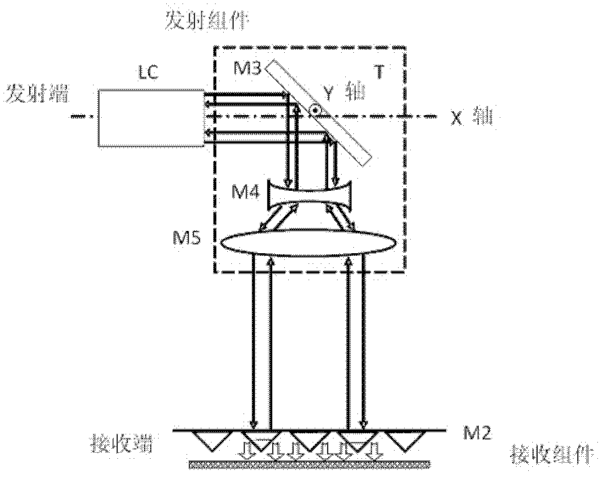
[0026] Embodiment 2: The difference between this embodiment and Embodiment 1 is that: the emission component includes multiple laser gain media. The tracking and aiming system includes: a 45° total reflection mirror for tracking and aiming at the receiving end by adjusting the incident angle of the laser emitted by the transmitting end. The beam expander includes a concave lens and a convex lens coaxial. like figure 2 As shown, the total reflection mirror M3, the concave lens M4 and the convex lens M5 constitute a two-dimensional turntable T, figure 2 The dotted box in the middle represents the two-dimensional turntable T. The 45 ° total reflection mirror M3, the concave lens M4 and the convex lens M5 are fixed on the two-dimensional turntable T and can rotate around the X axis and the Y axis at the center of the 45 ° total reflection mirror (⊙ indicates that the Y axis direction is from the inside of the paper to the outside of the paper ), to achieve two-dimensional sca...

Embodiment 3

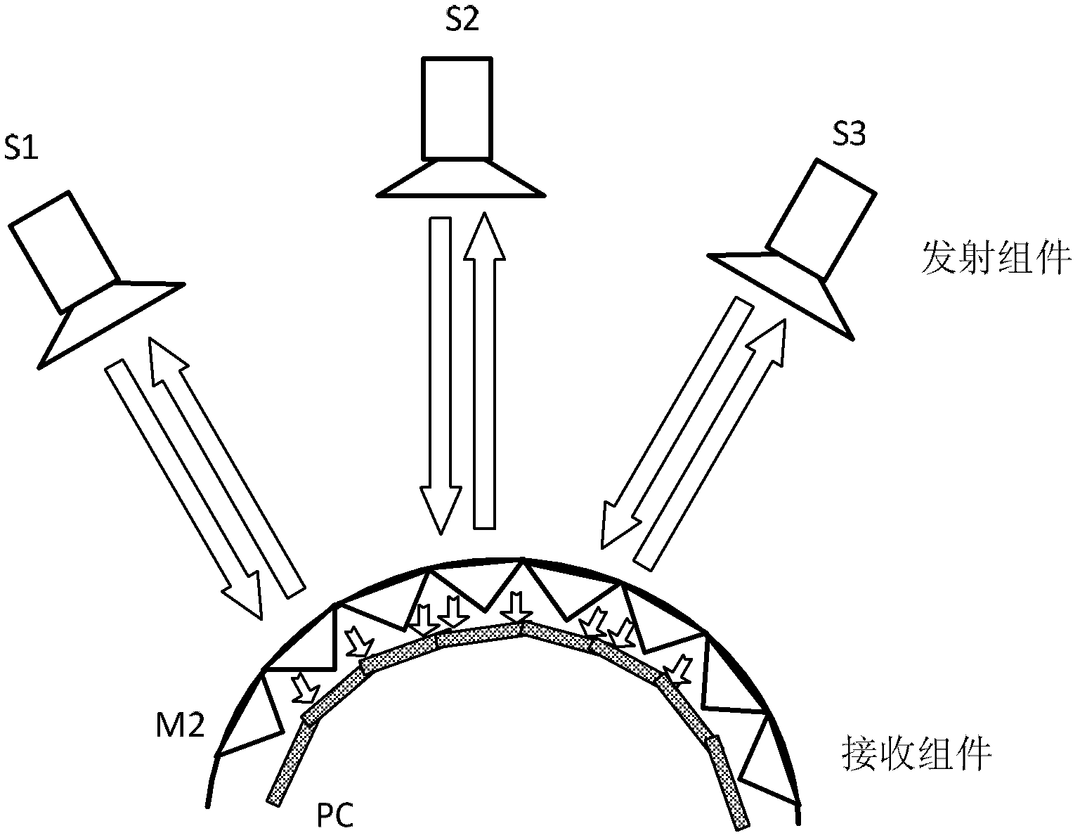
[0028] Embodiment 3: The difference between this embodiment and Embodiment 1 is that: the corner reflector array is a hemispherical corner reflector array composed of corner reflectors. The transmitting end includes multiple transmitting components. like image 3 As shown, the transmitting end includes a plurality of transmitting components S1, S2, S3...; the receiving end includes a receiving component. The corner reflector array M2 in the receiving component adopts a hemispherical corner reflector array composed of a plurality of pyramidal corner reflectors. Due to the directional reflection characteristics of the corner reflector array M2, the corner reflector array M2 can form a plurality of laser oscillators with a plurality of emitting components S1, S2, S3, . . . . The photovoltaic cell array PC located behind the hemispherical corner reflector M2 is also arranged in a hemispherical shape or directly fixed on the outer surface of the quadrangular pyramid corner reflec...


PUM


Abstract

The invention discloses a feedback type laser energy wireless transmission device. The feedback type laser energy wireless transmission device comprises a transmitting component which is positioned at a transmitting end and a receiving component which is positioned at a receiving end, wherein the transmitting component comprises a semiconductor laser and a beam expander; the receiving component comprises a photocell array; the transmitting component also comprises a tracking and alignment system which is used for tracking and alignment of the receiving end; and the receiving component also comprises a corner reflector array which is arranged in front of the photocell array and used for reflecting back a part of laser beam from the transmitting component, providing positive feedback for the semiconductor laser and transmitting the other part of laser beam to the photocell array. The feedback type laser energy wireless transmission device has the advantages that the corner reflector array is arranged at the receiving end, laser intensity which is transmitted by the transmitting end can be automatically adjusted by using an optical feedback effect according to the alignment of the transmitting end and the receiving end, the energy change of the receiving end is not required to be monitored in real time, and a laser energy transmission mechanism is high in safety and high in efficiency.

Description

technical field [0001] The invention relates to the technical field of wireless energy transmission, in particular to a feedback type laser energy wireless transmission device. Background technique [0002] Wireless energy transmission technology is a technology with broad application prospects in the aerospace and civil fields. It was first proposed by Nikola Tesla at the end of the 19th century. It has been developed to the present and there are mainly four transmission methods. Among them, two Short-distance transmission methods include: electromagnetic induction and magnetic resonance; two long-distance transmission methods include: microwave transmission and laser transmission. Compared with the electromagnetic induction method and the magnetic resonance method, the laser transmission method has the advantages of long transmission distance. Compared with the microwave transmission method, the laser transmission method has the advantages of short wavelength, small diverg...

Claims


Application Information

Patent Timeline
IPC IPC(8): H02J17/00H02N6/00H02J50/30
Inventor 尤政黄虎李滨王巍
Owner TSINGHUA UNIV
Learn More