Force-control-based magnetic levitation system and control method

A control system and magnetic levitation technology, applied in the field of magnetic levitation, can solve the problems that the bearing capacity of the magnetic bearing cannot reach the high-speed rotor, the displacement of the magnetic bearing cannot be directly measured, and the displacement sensor cannot be directly installed. simplified effect

Inactive Publication Date: 2012-09-12
UNIV OF JINAN
View PDF6 Cites 10 Cited by
  • Summary
  • Abstract
  • Description
  • Claims
  • Application Information

AI Technical Summary

Problems solved by technology

[0006] Second, the displacement sensor of the magnetic levitation system based on displacement control cannot be directly installed on the position of the magnetic bearing, so the displacement at the magnetic bearing cannot be directly measured. The complexity of the control system
[0008] Fourth, the bearing capacity of the magnetic bearing of the magnetic levitation system based on displacement control cannot meet the requirements of the high-speed rotor, and the bearing capacity is only provided by the magnetic bearing, and it is difficult to achieve a high-stiffness magnetic bearing
[0010] Due to the above-mentioned shortcomings of the maglev system based on displacement control, which largely limits the development of high-speed precision rotors, the existing technology still needs to be improved and developed

Method used


Image

  • Force-control-based magnetic levitation system and control method
  • Force-control-based magnetic levitation system and control method
  • Force-control-based magnetic levitation system and control method

Examples


Embodiment 1

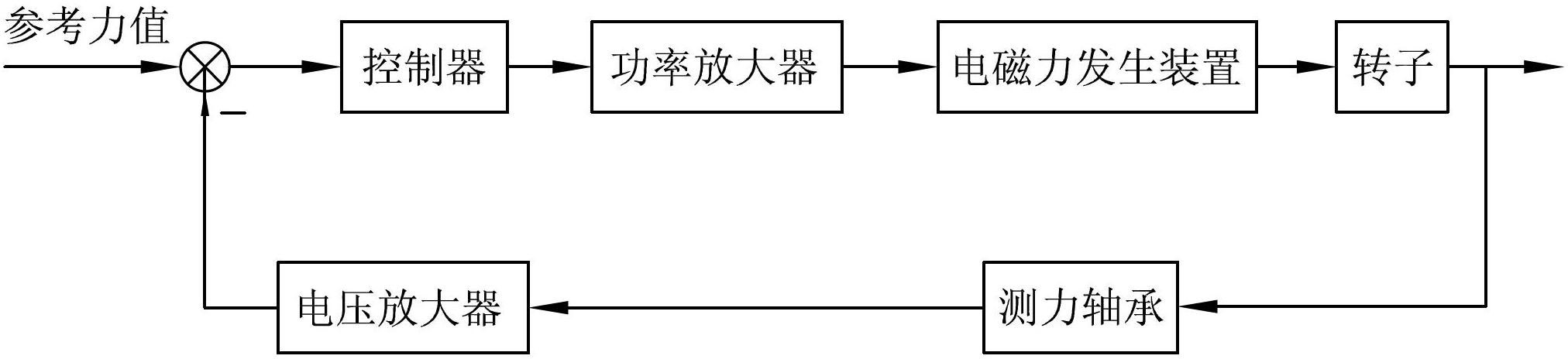
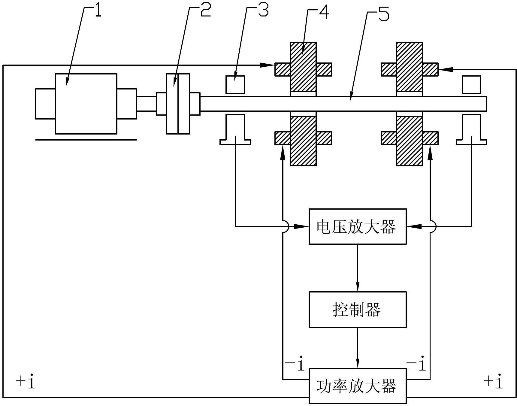
[0042] Such as figure 2 As shown, a magnetic levitation system based on force control includes a mechanical device and a control system. The mechanical device includes a motor 1, a shaft coupling 2, a force-measuring bearing 3, two radial magnetic bearings 4 and a rotor 5. The control system includes a voltage amplifier, a controller and a power amplifier. The motor 1 is connected to one end of the rotor 5 through a shaft coupling 2, the two ends of the rotor 5 are respectively provided with force-measuring bearings 3, and the two radial magnetic bearings 4 are arranged between the two force-measuring bearings 3 and Corresponding thereto; the input end of the voltage amplifier is connected with the force-measuring bearing, the output end is connected with the input end of the controller, the output end of the controller is connected with the input end of the power amplifier, and the output end of the power amplifier Connect with radial magnetic bearing 4. Wherein, the radial ...

Embodiment 2

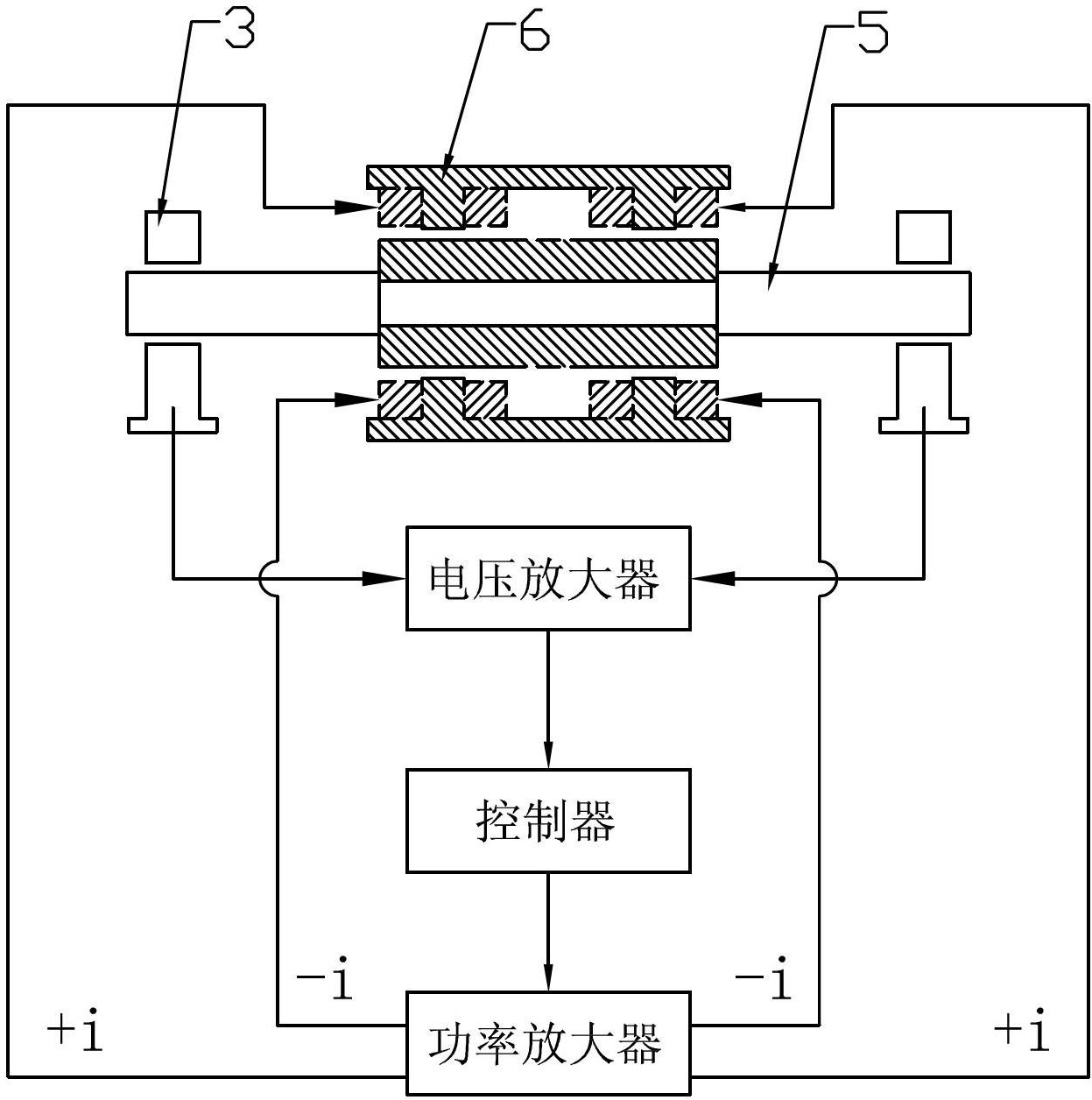
[0046] Such as image 3 As shown, a magnetic levitation system based on force control includes a mechanical device and a control system, the mechanical device includes a rotor 5, a quasi-levitation motor 6 and a load bearing 3, and the control system includes a voltage amplifier, a controller and a power amplifier . The two ends of the rotor 5 are respectively provided with a force-measuring bearing 3, and the quasi-levitation motor 6 is arranged between the two force-measuring bearings 3; the input end of the voltage amplifier is connected with the force-measuring bearing, and the output end is connected with the controller The input end of the controller is connected to the input end of the power amplifier, and the output end of the power amplifier is connected to the quasi-levitation motor; wherein, the quasi-levitation motor includes a torque coil sleeved on the rotor windings and quasi-suspension coil windings, the torque coil windings generate electromagnetic torque to ...

Embodiment 3

[0050] Such as Figure 4 As shown, a magnetic levitation system based on force control includes a mechanical device and a control system. The mechanical device includes a motor 1, a coupling 2, a load bearing 3, two radial magnetic bearings 4, a rotor 5 and an axial For a magnetic bearing, the control system includes a voltage amplifier, a controller and a power amplifier. The motor 1 is connected to one end of the rotor 5 through a coupling 2, and the two ends of the rotor 5 are respectively provided with force-measuring bearings 3, and the two radial magnetic bearings 4 are arranged between the two force-measuring bearings and respectively Correspondingly, the axial magnetic bearing is correspondingly arranged between two radial magnetic bearings 4; the input end of the voltage amplifier is connected to the force-measuring bearing, and the output end is connected to the input end of the controller, and the controller The output end of the power amplifier is connected to the...


PUM


Abstract

The invention discloses a force-control-based magnetic levitation system and a control method. The system comprises a mechanical device and a control system. The medical device comprises a rotor, an electromagnetic force generation device and dynamometric bearings. The control system comprises a voltage amplifier, a controller and a power amplifier. The dynamometric bearings are arranged at the two ends of the rotor. The electromagnetic force generation device is arranged between the dynamometric bearings at the two ends of the rotor. The input end of the voltage amplifier is connected with the dynamometric bearings, and the output end of the voltage amplifier is connected with the input end of the controller of which the output end is connected with the input end of the power amplifier. The output end of the power amplifier is connected with the electromagnetic force generation device. A displacement control method is replaced by the force control method, the quasi levitation of the rotor is realized, the complexity of a circuit system is lowered, and the system is simple in structure, convenient to construct and suitable for popularization and application, and is flexibly operated.

Description

technical field [0001] The invention relates to the technical field of magnetic suspension, in particular to a magnetic suspension system based on force control and a control method thereof. Background technique [0002] At present, in the magnetic levitation control system, the stable levitation of the rotor without contact is mainly achieved by controlling the displacement of the rotor from its equilibrium position. This control system is called a magnetic levitation system based on displacement control. Its main principle is that after the sensor detects the displacement of the rotor from the reference point, the controller converts the detected displacement into a control signal, and then the power amplifier converts the control signal into a control current, and the control current is in the actuator electromagnet A magnetic force is generated to drive the rotor back to its original balance position, maintaining its stable levitation position. [0003] At present, the ...

Claims


Application Information

Patent Timeline
Patent Type & Authority Applications(China)
IPC IPC(8): H02N15/00
Inventor 宋方臻冯会民宋波吴长忠邓良门秀花
Owner UNIV OF JINAN
Why Eureka
Try Eureka