Circuit for realizing passivity of intelligent photo wiring interface plate in port enabling way

An optical wiring and wiring technology, applied in the field of optical communication, can solve the problems of pollution and static electricity hazards, limit the operating space of the fiber fusion construction site, reduce the installation density of equipment, etc. Anti-static and anti-fouling ability, the effect of strong anti-static and anti-fouling ability

Active Publication Date: 2015-01-14
FENGHUO COMM SCI & TECH CO LTD
View PDF8 Cites 0 Cited by
  • Summary
  • Abstract
  • Description
  • Claims
  • Application Information

AI Technical Summary

Problems solved by technology

[0009] (1) The separation of fusion and matching deviates from the development direction of integration of fusion and matching, which reduces the installation density of equipment
[0010] (2) It is not that the distribution panel does not have optical fiber fusion splicing points, but it is only fused during equipment production to avoid on-site fusion, but this fusion point still cannot avoid failure during equipment operation, and it still faces on-site construction. Risk of Static Hazards
[0011] (3) A section of optical cable is added between the splicing tray and the distribution panel, which increases the cost of the equipment
[0012] (4) After the splicing tray is separated, it is still necessary to configure a splicing facility for factory splicing on the distribution panel, which also increases the cost of the equipment
[0013] (5) An optical fiber fusion splicing point is added to the equipment, which increases the loss of the line and reduces the reliability
[0014] (6) The fiber melting operation on the wiring board increases the production process of the equipment and increases the production cost of the equipment
[0015] (7) The optical cable between the fiber fusion tray and the distribution panel limits the on-site operation space of the fiber fusion construction, which is not conducive to improving the efficiency of on-site construction
[0018] In summary, although the introduction of electronic label technology in the ODN network for wiring management has obvious advantages, it needs to arrange circuits on the optical fiber distribution panel to manage the identity information of the optical fiber connectors, and the electronic circuit is easy to manage. The defects of static electricity hazards and sewage short-circuit damage make it difficult for wiring equipment to withstand the harsh working environment of equipment site construction, which can easily cause machine disk damage

Method used


Image

  • Circuit for realizing passivity of intelligent photo wiring interface plate in port enabling way
  • Circuit for realizing passivity of intelligent photo wiring interface plate in port enabling way
  • Circuit for realizing passivity of intelligent photo wiring interface plate in port enabling way

Examples


Embodiment 1

[0061] Embodiment 1: Combining machine disk read and write control + grouping port enablement.

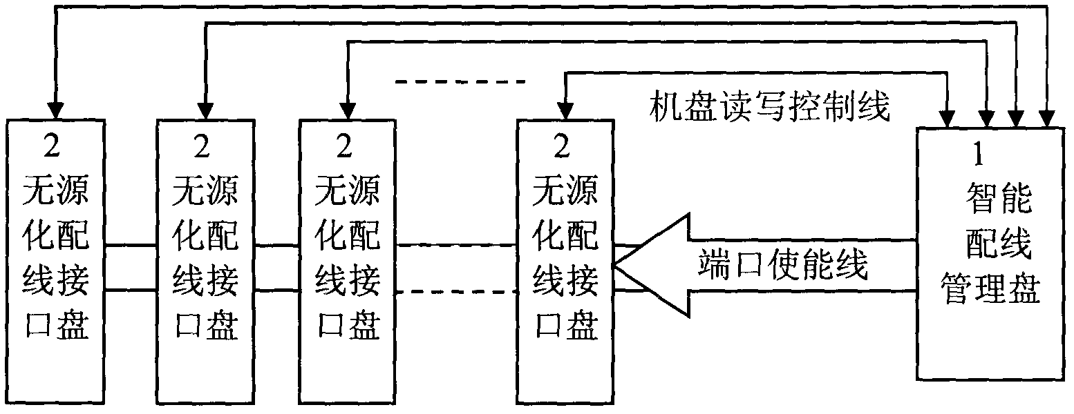
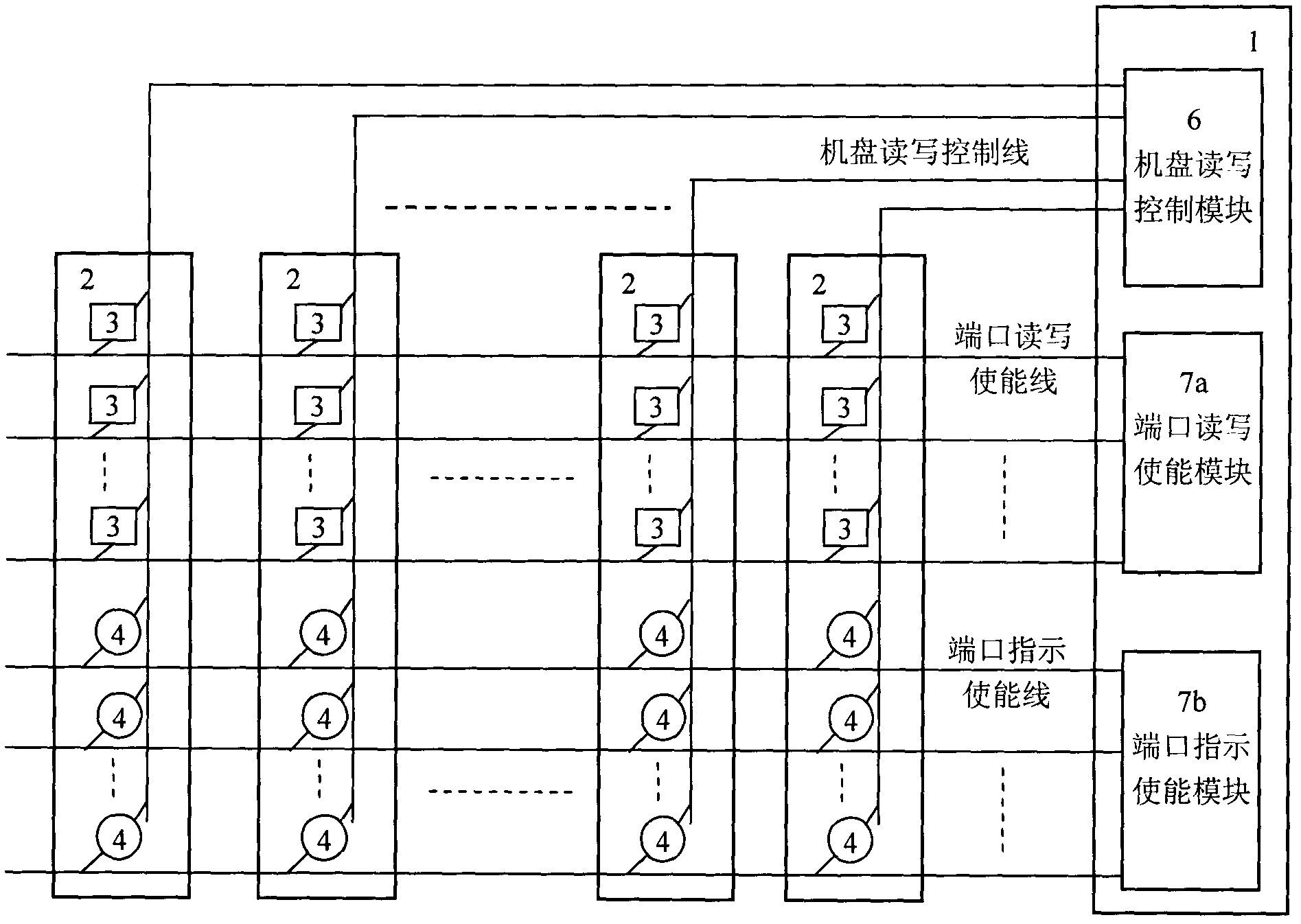
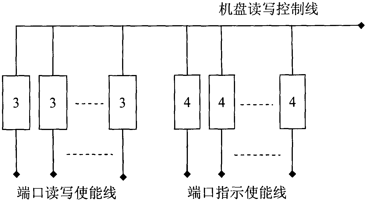
[0062] see figure 2 As shown, the intelligent wiring management disk 1 includes a machine disk read-write control module 6, a port read-write enable module 7a and a port indication enable module 7b, see image 3 As shown, the signal read-write end of each wiring information read-write interface 3 in each passive wiring interface panel 2 and the display control end of each wiring port indicator 4 are connected together and drawn out as the passive The machine disk read and write control terminal of wiring interface disk 2. see figure 2 As shown, the disk read-write control module 6 leads out several disk read-write control lines, which are respectively connected to the disk read-write control terminals of the passive wiring interface disks 2 .

[0063] see image 3 As shown, the reference control terminals of each wiring information read-write interface 3 in each passive wirin...

Embodiment 2

[0064] Embodiment 2: group machine disk read and write control + group port enable.

[0065] In order to further increase the port management capacity of the bus, or manage ports for classification, each port device that needs to be managed can be managed in groups.

[0066] see Figure 4 As shown, the intelligent wiring management disk 1 includes a machine disk information read-write module 6a, a machine disk indication control module 6b, a port read-write enable module 7a and a port indication enable module 7b, see Figure 5 As shown, the signal read-write terminals of each wiring information read-write interface 3 in each passive wiring interface panel 2 are connected together as the disk information read-write terminal of the passive wiring interface panel 2, with Accept the read and write control of the machine disk port of the intelligent wiring management panel 1; The panel port indication control of the wiring management panel.

[0067] The disk read-write control l...

Embodiment 3

[0069] Embodiment 3: Group machine disk read and write control + combined port enablement.

[0070] see Image 6 As shown, the intelligent wiring management panel 1 includes a machine disk information reading and writing module 6a, a machine disk indication control module 6b and a port enabling module 7, see Figure 7 As shown, the signal read-write terminals of each wiring information read-write interface 3 in each passive wiring interface panel 2 are connected together as the disk information read-write terminal of the passive wiring interface panel 2, each The display control terminals of the wiring port indicator 4 are connected together as the machine panel indicating control terminal of the passive wiring interface panel 2 . The disk read-write control line in this embodiment is divided into the disk information read-write line and the disk indication control line, see Image 6 As shown, the machine disk information reading and writing module 6a leads to several machin...


PUM


Abstract

The invention discloses a circuit for realizing passivity of an intelligent photo wiring interface plate in a port enabling way, belonging to the field of photo communication; the circuit comprises an intelligent wiring management plate, and a plurality of wiring interface plates connected with the intelligent wiring management plate, respectively; the circuit further comprises a plurality of plate reading and writing control lines and a plurality of port enabling lines; all the wiring interface plates are passive wiring interface plates; each passive wiring interface plate is connected with the intelligent wiring management plate through the plate reading and writing control line corresponding to the passive wiring interface plate; the intelligent wiring management plate is further connected with the passive wiring interface plates through a plurality of port enabling lines, so as to perform the centralized management on the passive wiring interface plates in a matrix way. According to the invention, the wiring ports are separated from the wiring management, management circuits on the wiring interface plate are all moved out, all control and management functions are realized on the wiring management plate, so that the circuit of the wiring interface plate is passive; the wiring plates have extremely high anti-static property and staining resistance in the site operation.

Description

technical field [0001] The invention relates to the field of optical communication, in particular to a circuit for realizing passiveization of an intelligent optical distribution interface board in a port-enabling manner. Background technique [0002] Driven by the construction of FTTH (Fiber-To-The-Home, fiber-to-the-home), the global ODN (Optical Distribution Network, Optical Distribution Network) ushered in explosive growth. Since FTTH mainly adopts PON (Passive Optical Network, Passive Optical Network) technology, it shunts an OLT (Optical Line Terminal, Optical Line Terminal) to dozens or hundreds of ONUs (Optical Network Unit, Optical Network Unit), which As a result, a huge amount of optical fiber lines are generated at the user end of the ODN network, which requires wiring scheduling, maintenance and management. [0003] The early optical cable lines were basically point-to-point lines, and the management was relatively easy. However, the ODN network serving FTTH is...

Claims


Application Information

Patent Timeline
Patent Type & Authority Patents(China)
IPC IPC(8): H04Q1/14H04Q1/20H04B10/25
Inventor 雷非肜云陈海成张丹罗雄豹
Owner FENGHUO COMM SCI & TECH CO LTD
Why Eureka
Try Eureka