Highly-efficient light emitting diode (LED) power supply

A technology of LED power supply and LED light source, applied in electric light source, light source, electric lamp circuit layout and other directions, can solve the problems of high power supply cost, increase hidden trouble of failure, and high cost, increase LED temperature compensation function, reduce production cost and failure rate , The effect of reducing the temperature of the working environment

Inactive Publication Date: 2012-09-12
无锡联力电子科技股份有限公司
View PDF1 Cites 2 Cited by
  • Summary
  • Abstract
  • Description
  • Claims
  • Application Information

AI Technical Summary

Problems solved by technology

[0005] 1. Low efficiency and large volume
The traditional switching power supply method needs to use an isolation transformer on the main circuit. When the transformer is working, it will lose 10% to 30% of the energy, resulting in low efficiency of the entire circuit.
At the same time, the transformer is generally larger in size
The use of a transformer leads to a large volume of the entire power supply, which cannot meet the requirements for installation and use in some small spaces
[0006] 2. The circuit is complicated and the cost is high
Due to the use of an independent constant current chip circuit, the circuit structure is relatively complicated, which not only increases the hidden danger of failure, but also brings inconvenience to maintenance
Using an isolation transformer, because the transformer and the chip are high-value components in the circuit, the cost of the entire power supply is high, which is not conducive to mass production and application
[0007] 3. Unable to control LED working temperature
[0009] However, at present, the driving current of most LEDs is designed as a constant current source that does not change with temperature. Therefore, when the ambient temperature of the LED is higher than the safe temperature point, the operating current is not in the safe area, which will cause the life of the LED to be much lower than the specification The value of the book is even directly damaged

Method used


Image

  • Highly-efficient light emitting diode (LED) power supply
  • Highly-efficient light emitting diode (LED) power supply
  • Highly-efficient light emitting diode (LED) power supply

Examples


Embodiment Construction

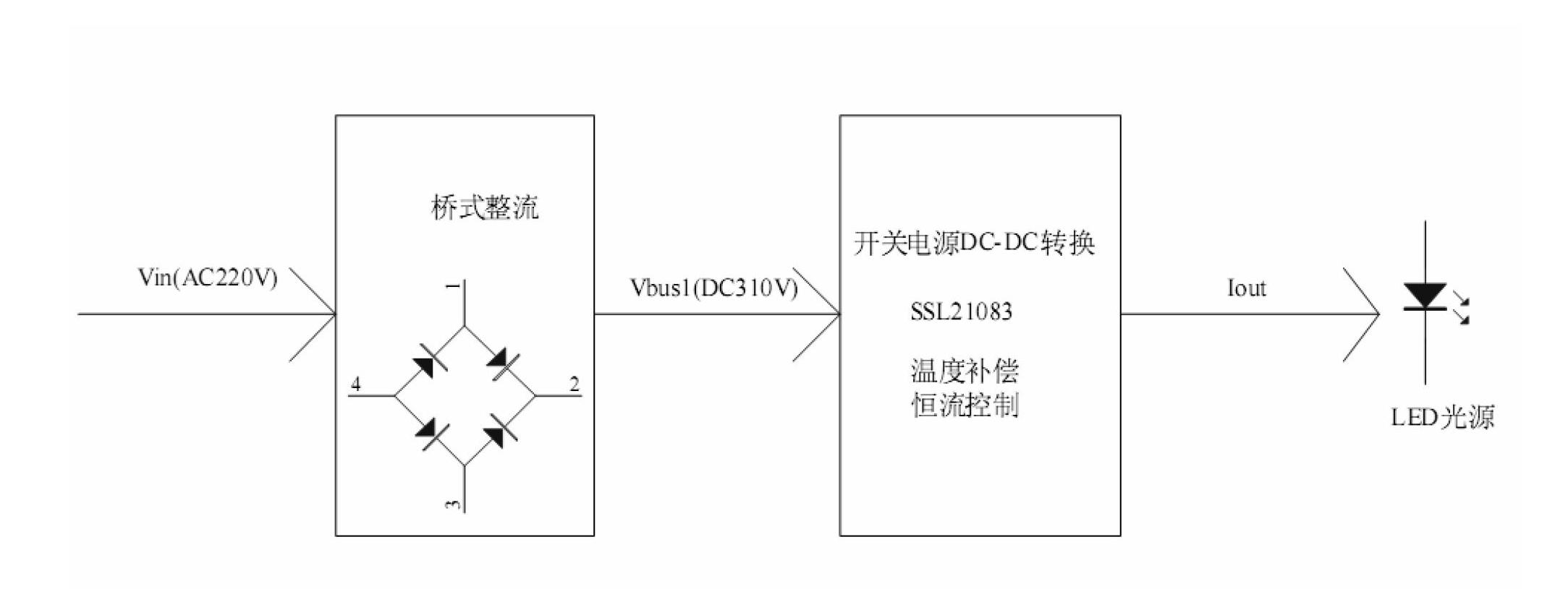
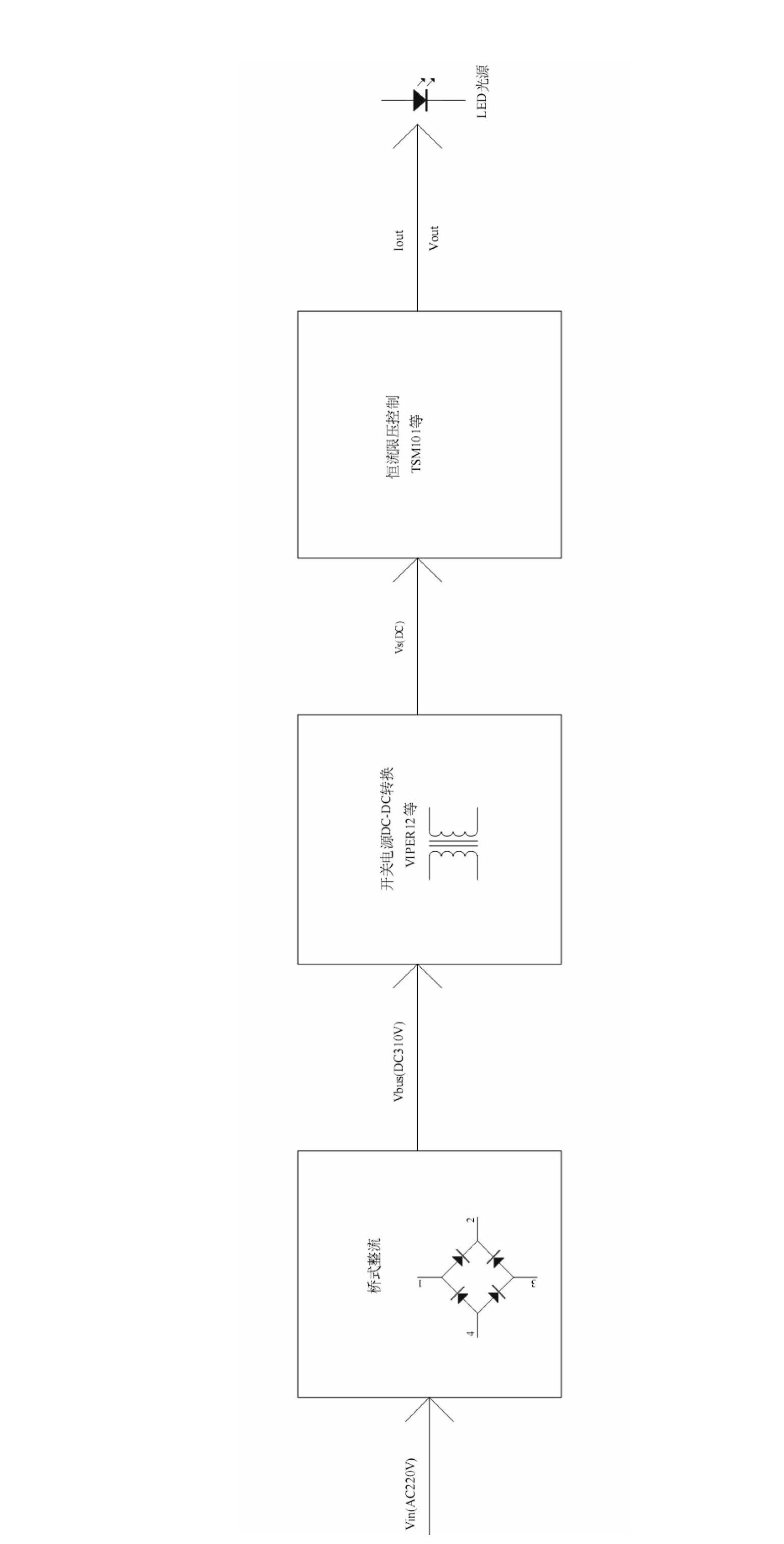
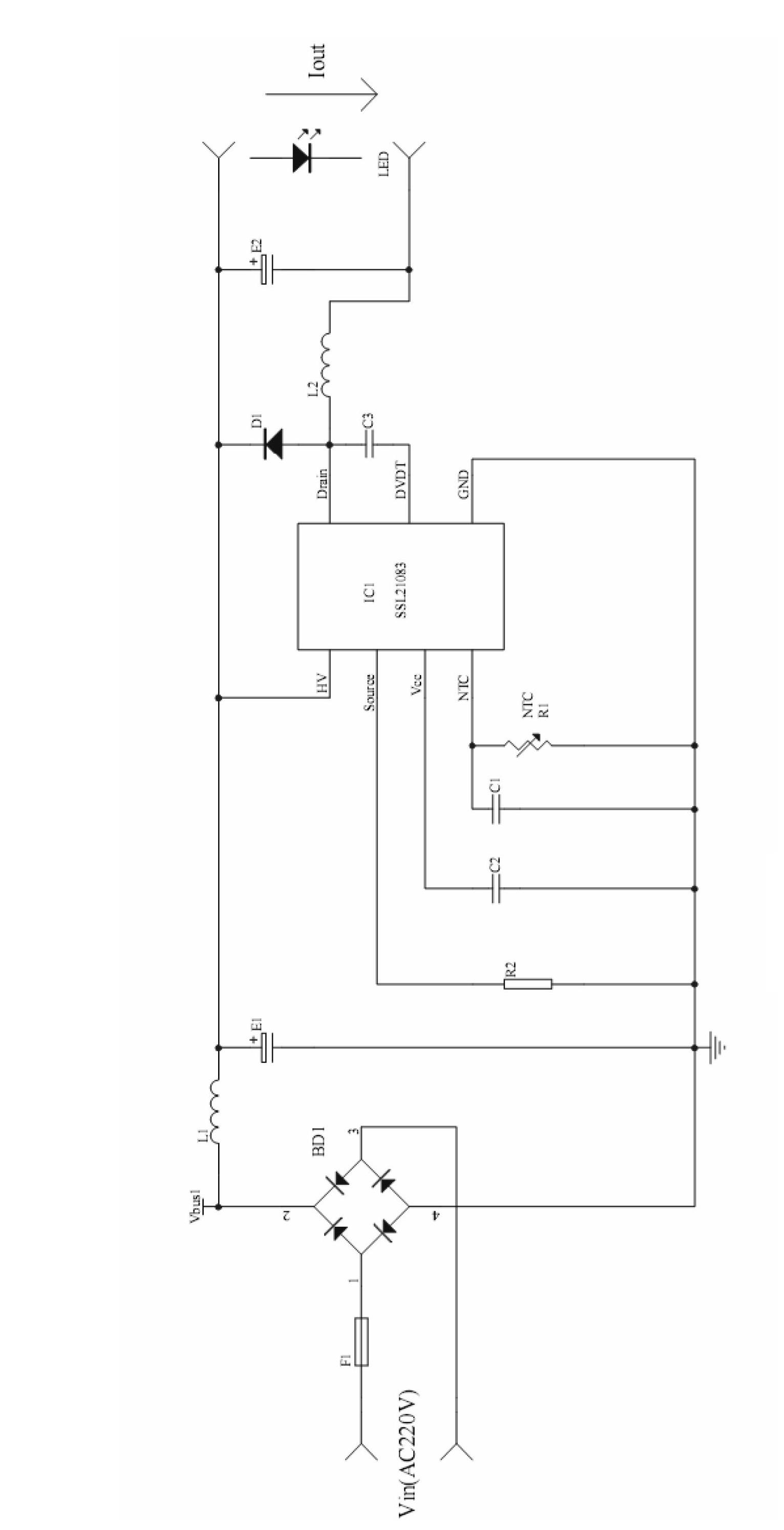
[0021] The present invention will be further described below in conjunction with drawings and embodiments. The present invention is used for LED lighting with AC 220V input and constant current output, including a bridge rectifier module and a switching power supply DC-DC conversion module. The output end of the bridge rectification module is connected to the LED light source through the switching power supply DC-DC conversion module, such as figure 2 shown. Specific circuit such as image 3 shown, including:

[0022] 1. Bridge rectifier module. Used to convert AC input into DC voltage Vbus1.

[0023] 2. Switching power supply conversion chip SSL21083 and peripheral circuits.

[0024] Such as image 3 , The power supply is a step-down BUCK circuit.

[0025] The rectifier bridge BD1 of the bridge rectifier module converts the AC input into a DC voltage Vbus1, and the waveform of Vbus1 is in the form of a half sine wave. The positive pole of the rectifier bridge BD1 is c...


PUM


Abstract

The invention relates to a highly-efficient light emitting diode (LED) power supply. The power supply comprises a bridge rectifier module and a switching power supply direct current-direct current (DC-DC) conversion module, wherein the output end of the bridge rectifier module is connected to an LED light source through the switching power supply DC-DC conversion module; and the switching power supply DC-DC conversion module comprises a secure sockets layer (SSL) 21083 chip. The highly-efficient LED power supply has the advantages that the work efficiency of the power supply is greatly improved, the size of the power supply is reduced, and the product cost is reduced by eliminating a transformer and an independent constant current control circuit; and the operating temperature of an LED is controlled, the over temperature protection of the LED light source is realized, and the service life of the power supply and a lamp is prolonged by an LED temperature compensation circuit of the power supply.

Description

technical field [0001] The invention relates to a power supply circuit, in particular to a high-efficiency LED power supply. Background technique [0002] As a new lighting method, LED has the advantages of long life, low energy consumption, no mercury pollution, flexible application, etc., and has broad development prospects. Most of the current LED power supplies use a constant current output control scheme, which requires an isolation transformer. [0003] Such as figure 1 As shown, the existing constant current output control scheme first rectifies the AC input into Vbus1, and then converts the high-voltage DC Vbus1 into the required low-voltage DC Vs through a transformer through a traditional DC-DC switching power supply circuit, such as VIPER12. Vs then passes through a constant current circuit such as TSM101 to obtain the Vout required by the load. [0004] The most important problem that existing circuit exists is: [0005] 1. Low efficiency and large volume. T...

Claims


Application Information

Patent Timeline
Patent Type & Authority Applications(China)
IPC IPC(8): H05B37/02
Inventor 陈忠胜陈辉斌
Owner 无锡联力电子科技股份有限公司
Why Eureka
Try Eureka