In-wheel motor driving device

A technology of driving device and in-wheel motor, applied in the direction of gear transmission device, power device, transmission device, etc., can solve problems such as difficulty in implementation

Inactive Publication Date: 2012-09-12
NTN CORP
View PDF7 Cites 12 Cited by
  • Summary
  • Abstract
  • Description
  • Claims
  • Application Information

AI Technical Summary

Problems solved by technology

As a means of reducing the weight of the in-wheel drive itself, thinning of the casing m

Method used


Image

  • In-wheel motor driving device
  • In-wheel motor driving device
  • In-wheel motor driving device

Examples


Example Embodiment

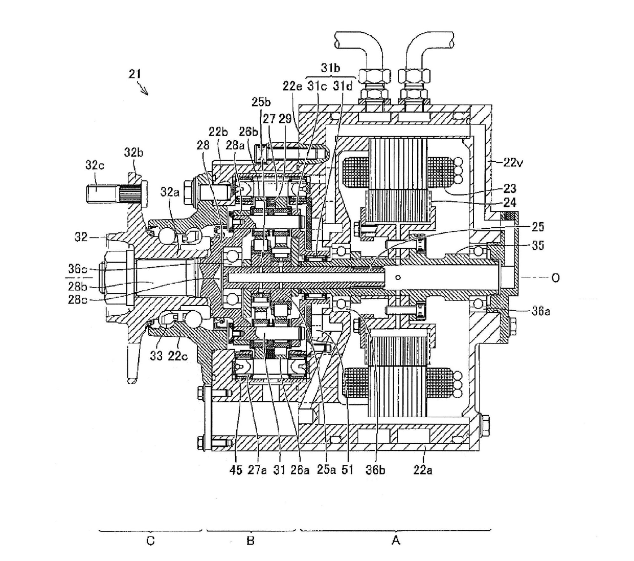
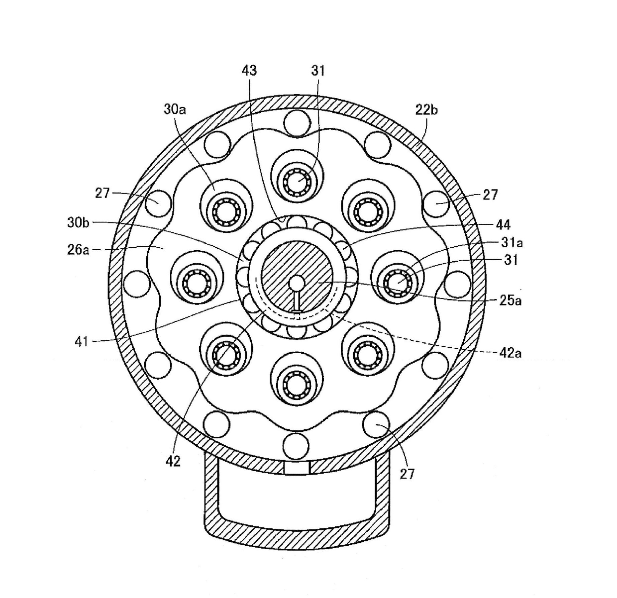
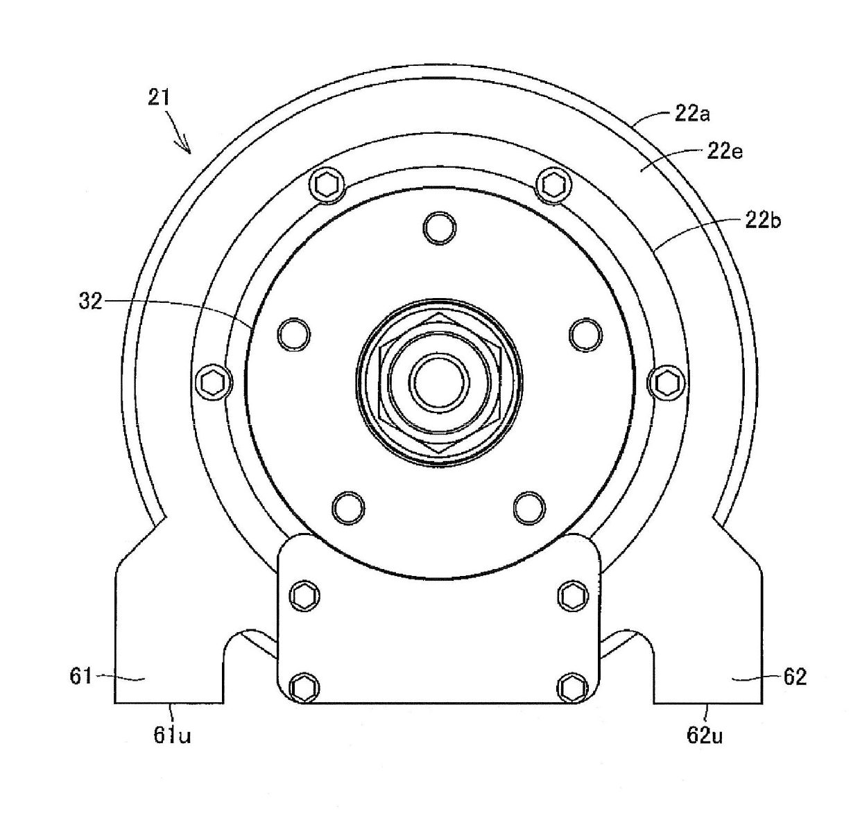
[0060] Hereinafter, embodiments of the present invention will be described in detail based on Examples shown in the drawings. figure 1 It is a longitudinal sectional view showing the in-wheel motor driving device according to the first embodiment of the present invention. figure 2 is a transverse cross-sectional view showing the deceleration unit of this embodiment. image 3It is a front view showing the state of this Example seen from one side in the axial direction.

[0061] The in-wheel motor driving device 21 that is arranged in the hollow area of ​​the running wheel in the wheel to drive the wheel includes: a motor part A that generates driving force; a deceleration part B that decelerates the rotation of the motor part A and outputs it; The output is the wheel hub bearing portion C which is transmitted to a wheel not shown. In addition, the motor unit A, the deceleration unit B, and the wheel hub bearing unit C are sequentially arranged in series and coaxially. The i...


PUM


Abstract

An in-wheel motor driving device (21) is provided with a motor section (A); a speed reduction section (B) which comprises an output shaft (28) that reduces the rotational speed of a motor rotation shaft (35) and outputs the resulting rotation, and a speed reduction section casing (22b) that forms an outer shell, this speed reduction section (B) being disposed at one location along the axial direction of the motor section (A); a wheel hub bearing section (C) which comprises a wheel hub (32) that is connected and fixed to the output shaft (28), and a wheel hub bearing outer race (22c) that rotatably supports the wheel hub (32), this wheel hub bearing section (C) being disposed at one location along the axial direction of the speed reduction section (B); and connection sections (63, 64) which are fixed to at least one of either the wheel hub bearing outer race (22c) or the speed reduction section casing (22b) and are meant to be connected to a vehicle body member.

Description

technical field [0001] The present invention relates to an in-wheel motor driving device for driving a wheel, and more particularly relates to a mounting structure with a suspension member such as a trailing arm, a lower arm, or a shock absorber. Background technique [0002] In recent years, in the technical field of vehicles, an in-wheel motor driving device that drives a wheel by arranging part or all of it in an inner space of a running wheel has attracted attention. For example, a conventional in-wheel motor drive device is described in JP-A-2008-44537 (Patent Document 1). In the in-wheel motor drive device described in Patent Document 1, a drive motor, a speed reducer that inputs drive force from the drive motor and decelerates the rotational speed to output to the wheel side, and a hub member of the wheel coupled to the output shaft of the speed reducer are coaxial and Tandem configuration. This speed reducer is a cycloid speed reduction mechanism, and can obtain a ...

Claims


Application Information

Patent Timeline
IPC IPC(8): B60K7/00B60G7/00F16H1/32
CPCB60K7/0007B60G3/20B60G2204/148B60G2204/30B60G2300/50B60K17/043B60K17/046B60K2007/0038B60K2007/0092F16H1/32
Inventor 山本哲也山形哲
Owner NTN CORP
Why Eureka
Try Eureka