Vehicle body panel joining structure

A body panel and structure technology, applied in the field of body panel joint structure, can solve the problems of reduced impact load transferability, obstruction of connecting parts, increase in the number of parts, etc., and achieve the effect of improving the rigidity of the body and suppressing the reduction of the strength of the body

Active Publication Date: 2012-09-12
HONDA MOTOR CO LTD
View PDF7 Cites 7 Cited by
  • Summary
  • Abstract
  • Description
  • Claims
  • Application Information

AI Technical Summary

Problems solved by technology

[0006] However, in the vehicle body manufacturing form in which the floor assembly centered on the floor panel is placed on the front body assembly including the connecting member and spot welded, the instrument panel lower member and the underbody that separate the vehicle compartment and the engine compartment The joining part of the panel is located in the back side of the connecting member, and the connecting member will hinder the spot welding, so it is necessary to provide a hole for inserting the welding gun in the connecting member
[0007] Therefore, a cover for closing the hole is required, and there is a problem that the number of parts increases, and there is a problem that a precise jig is required in order to accurately align and combine the positions of the holes.
In addition, there is a problem that the transferability of the impact load at the portion where the hole is provided decreases

Method used


Image

  • Vehicle body panel joining structure
  • Vehicle body panel joining structure
  • Vehicle body panel joining structure

Examples


Embodiment Construction

[0025] Next, an embodiment of the present invention will be explained based on the drawings.

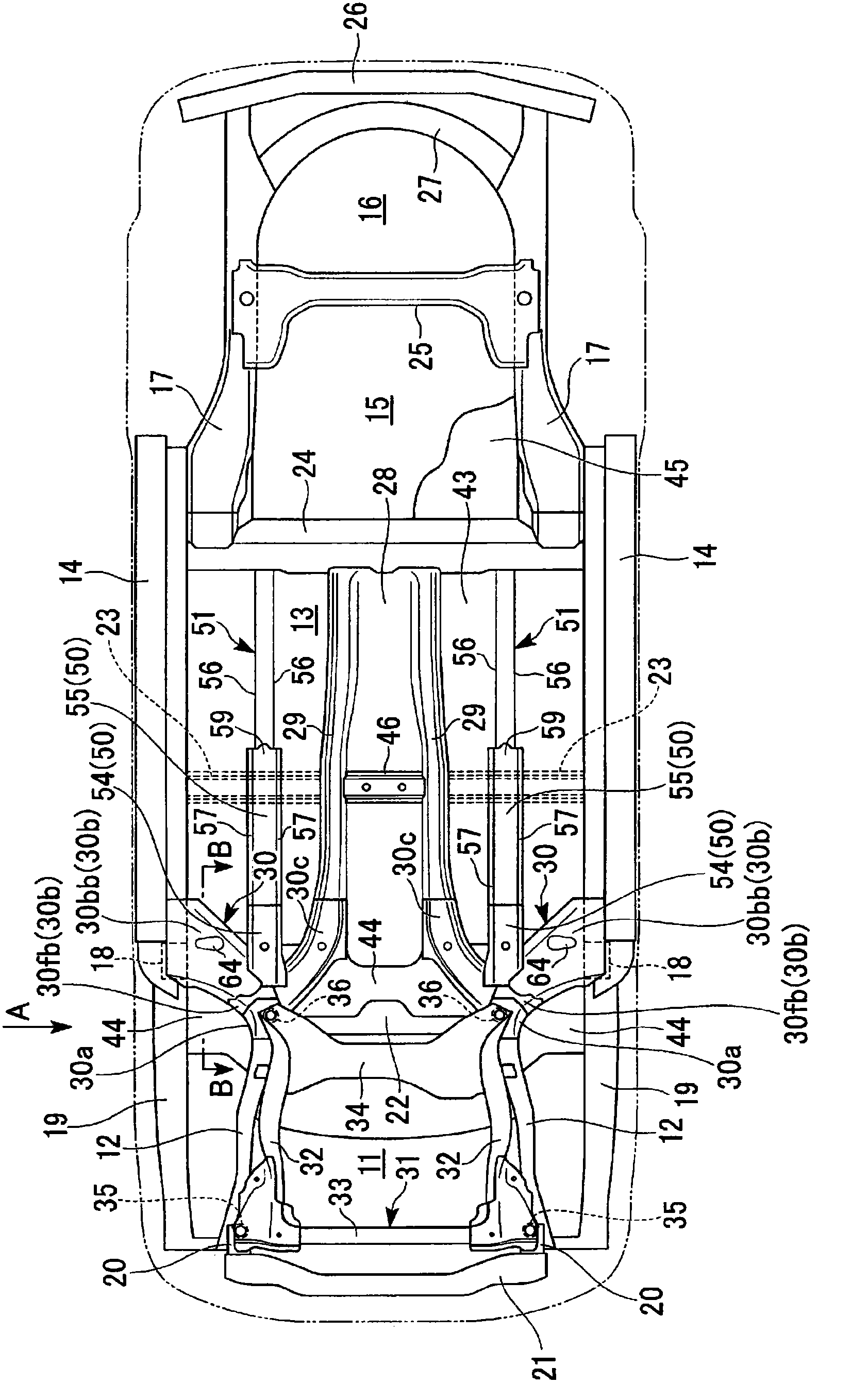
[0026] figure 1 Is a view of the car body viewed from the bottom surface, figure 2 Yes figure 1 The A-direction view. In addition, in figure 1 , figure 2 The outline of the car body is indicated by a dotted line in the middle. Such as figure 1 , figure 2 As shown, the vehicle body frame has: a pair of left and right closed cross-sectional structure front frames 12, 12 extending along the left and right sides of the engine room 11 and extending in the front and rear direction of the vehicle body; A pair of left and right side members 14 and 14 with a closed cross-sectional structure extending in the front and rear direction of the vehicle body; extending along the left and right sides of the fuel tank storage portion 15 and the luggage compartment 16 in the front and rear direction of the vehicle body , A pair of left and right rear frames 17 and 17 with closed cross-section structur...


PUM


Abstract

Disclosed is a vehicle body panel joining structure which is provided with: a structural frame (30b) having a ridge line in the lengthwise direction, which has one section joined to a first vehicle body panel (44) and another section joined to a second vehicle body panel (43); an overlap part (61) which overlaps the first and second vehicle body panels and is disposed in such a way that the structural frame straddles the overlap part; a depressed part (64) which is provided at a position avoiding the ridge line on the structural frame and is abutted by the overlap part; and a spot-welded part (65) which is joined to the depressed part, the first vehicle body panel and the second vehicle body panel at the overlap part by means of spot welding.

Description

Technical field [0001] The present invention relates to a vehicle body panel joining structure. [0002] This application claims priority based on Japanese Patent Application No. 2009-285133 for which it applied to Japan on December 16, 2009, and the content is used here. Background technique [0003] Known is a vehicle body structure provided with connecting members. The connecting members are arranged on the rear end of the front frame on both sides of the engine room in the front and rear direction, and are arranged under the both sides of the cabin in the front and rear direction. The front end portion of the side sill is connected to the front end portion of the center frame arranged in the center portion of the vehicle width direction of the vehicle cabin in the front-rear direction. [0004] Because the connecting member has: an outrigger extending toward the outside in the vehicle width direction and obliquely rearward and connected to the front end of the side member; and a...

Claims


Application Information

Patent Timeline
Patent Type & Authority Applications(China)
IPC IPC(8): B62D25/20
CPCB62D21/155B23K11/115B23K2101/006B62D21/11B62D25/2018B62D27/023
Inventor 安原重人松浦裕志菅原克也
Owner HONDA MOTOR CO LTD
Why Eureka
Try Eureka