Infrared sensor

An infrared sensor and infrared technology, applied in the direction of instruments, scientific instruments, electric radiation detectors, etc., can solve the problems of increasing the distance of heat-sensitive elements, high thermal conductivity of resin films, and high prices, so as to improve thermal responsiveness and detection sensitivity , high sensitivity, compact and well-made effects

Active Publication Date: 2012-09-12
MITSUBISHI MATERIALS CORP
View PDF5 Cites 5 Cited by
  • Summary
  • Abstract
  • Description
  • Claims
  • Application Information

AI Technical Summary

Problems solved by technology

[0008] That is, in the infrared sensors of Patent Documents 1 and 2, a resin film containing an infrared absorbing material such as carbon black is adopted, and one thermal sensor side is shielded from light for the purpose of temperature compensation. The thermal conductivity of the resin film is high, and it is difficult to cause a temperature difference between the thermal sensor for infrared detection and temperature compensation.
Also, in order to increase the temperature difference between these heat-sensitive elements, it is necessary to increase the distance between the heat-sensitive elements, resulting in a large overall shape, and there is a problem that miniaturization is difficult
In addition, it is necessary to provide a structure for shielding the thermal sensor for temperature compensation on the case itself, so the price becomes high.
[0009] In addition, in Patent Document 2, since a housing with good heat conduction is used, the heat from the infrared absorbing film is also dissipated to cause a disadvantage in that the sensitivity deteriorates.
In addition, since it is a loose-leaf type connected with a lead wire, it causes heat conduction in a space between the thermistor and the lead wire
In addition, in the case of a loose leaf type or a chip type thermistor, there is a disadvantage that a measurement error occurs when the resin film produces an in-plane distribution of temperature due to spot measurement.

Method used


Image

  • Infrared sensor
  • Infrared sensor
  • Infrared sensor

Examples


Embodiment Construction

[0034] Below, reference Figure 1 ~ Figure 4 The first embodiment of the infrared sensor according to the present invention will be described. In addition, in each drawing used in the following description, in order to make each component a recognizable or easily recognizable size, the scale is appropriately changed.

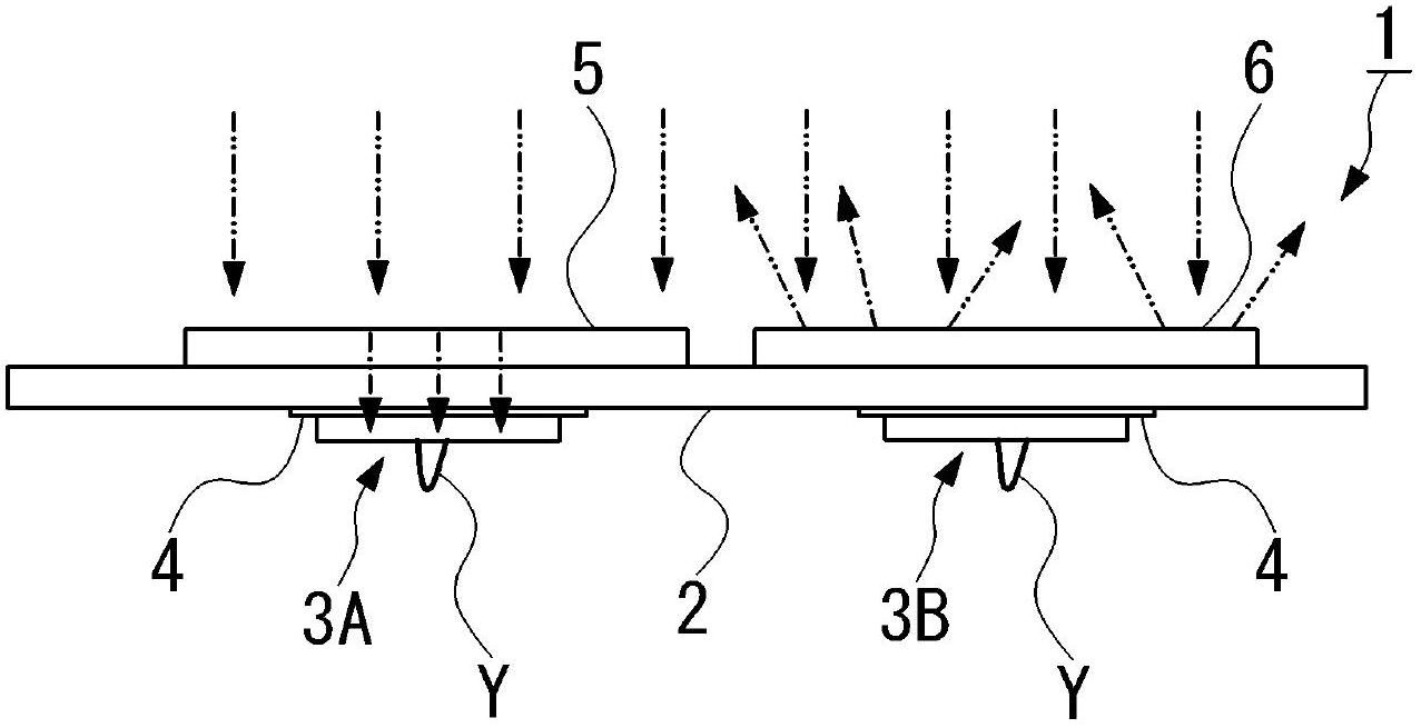
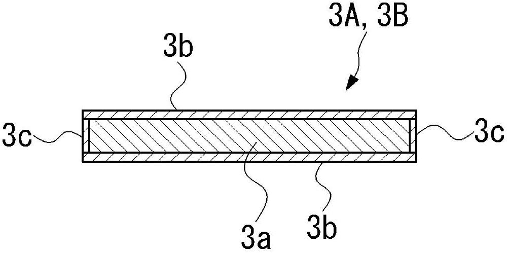
[0035] Such as figure 1 and figure 2 As shown, the infrared sensor 1 of the present embodiment includes: an insulating film 2; a first thermal element 3A and a second thermal element 3B, which are spaced apart from each other on one surface (lower surface) of the insulating film 2; For the bonding electrode 4, the insulating film 2 is patterned with copper foil or the like on one side, and the first heat-sensitive element 3A and the second heat-sensitive element 3B; the infrared absorption film 5 and the first heat-sensitive element 3A are bonded respectively Opposite and provided on the other side (upper surface) of the insulating film 2; and the infrared reflec...


PUM


Abstract

Disclosed is an infrared sensor which is able to obtain a large temperature difference between a heat sensitive element for infrared ray detection and a heat sensitive element for temperature compensation, as well as has an inexpensive structure which is conducive to a compact assembly. The infrared sensor comprises an insulating film (2); a first heat sensitive element (3A) and a second heat sensitive element (3B) spaced apart from each other on one face of the insulating film (2); a pair of adhesive electrodes (4), formed on one face of the insulating film (2), to which the first heat sensitive element (3A) and the second heat sensitive element (3B) adhere respectively; an infrared absorbing film (5) arranged on the other face of the insulating film (2) opposite the first heat sensitive element (3A); and an infrared reflecting film (6) arranged on the other face of the insulating film (2) opposite the second heat sensitive element (3B). The first heat sensitive element (3A) and the second heat sensitive element (3B) have a tabular thermistor body (3a) and a pair of electrode layers formed respectively on front and back surfaces of the thermistor body (3a), with one of the electrode layers adhering to the adhesive electrode (4).

Description

Technical field [0001] The present invention relates to an infrared sensor that detects infrared rays from an object to be measured and measures the temperature of the object to be measured. Background technique [0002] Conventionally, an infrared sensor has been used as a temperature sensor that detects the infrared radiation emitted from the measurement target in a non-contact manner to measure the temperature of the measurement target. [0003] For example, Patent Document 1 proposes an infrared sensor which is provided with a resin film provided on a holder, an infrared detecting thermal element that is provided on the resin film and detects infrared rays through a light guide portion of the holder, and is installed in a light-shielding state Thermal element for temperature compensation used in resin film to detect the temperature of the holder. In this infrared sensor, an infrared absorbing film is formed on the inner surface of the light guide portion, and the resin film co...

Claims


Application Information

Patent Timeline
Patent Type & Authority Applications(China)
IPC IPC(8): G01J5/20G01J1/02
CPCG01J5/10G01J5/064G01J5/80G01J1/02G01J5/20
Inventor 中村贤蔵北口诚石川元贵
Owner MITSUBISHI MATERIALS CORP
Why Eureka
Try Eureka