Cyclone dust collector with spiral air inlet pipe

A technology of cyclone dust collector and air inlet pipe, which is applied in the direction of the device where the axial direction of the swirl flow can be reversed, the swirl flow device, etc., which can solve the problem of secondary dust raising, affecting the dust removal efficiency of the dust collector, and gas-solid separation of the dust collector Performance degradation and other problems, to achieve high separation efficiency and reduce the effect of secondary dust

Inactive Publication Date: 2012-09-19
郭丰亮
View PDF4 Cites 8 Cited by
  • Summary
  • Abstract
  • Description
  • Claims
  • Application Information

AI Technical Summary

Problems solved by technology

[0004] However, the axis of the air inlet pipe in the existing cyclone dust collector with tangential inlet form is perpendicular to the axis of the cyclone inside the volute. Since the airflow enters the dust collector from the upper tangential direction and rotates downward, this will inevitably cause the top of the dust collector to empty. The vortex air flow is formed to generate the top ash ring. When the ash ring rotates downward along the guide vanes on the exhaust pipe, it will mix with the upcycled air flow of the purified exhaust gas at the entrance of the exhaust pipe, forming a secondary wind problem. It affects the dust removal efficiency of the dust collector; secondly, the air inlet pipe of the existing dust collector is blown directly into the cylinder, and the airflow rotates after entering the cylinder. Reduce the gas-solid separation performance of the dust collector

Method used


Image

  • Cyclone dust collector with spiral air inlet pipe
  • Cyclone dust collector with spiral air inlet pipe

Examples


Embodiment Construction

[0013] The preferred embodiments of the present invention will be described in detail below in conjunction with the accompanying drawings, so that the advantages and features of the present invention can be more easily understood by those skilled in the art, so as to define the protection scope of the present invention more clearly.

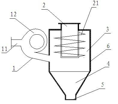
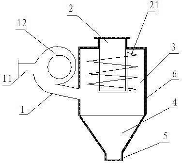
[0014] see figure 1 , the embodiment of the present invention comprises: air inlet pipe 1, cyclone 3, air exhaust pipe 2, spiral guide vane 21, conical ash collector 4 and ash discharge port 5, and air inlet pipe 1 is arranged on one side of cyclone 3 , the spiral guide vane 21 is fixed on the exhaust pipe 2 and the lower end extends into the cyclone 3, the lower end of the cyclone 3 is connected with a conical ash collector 4 communicating with the cyclone 3, and the lower end of the ash collector 4 is provided with an ash discharge port 5. The air inlet pipe 1 is a spiral pipe 12 structure, one end is an air inlet 11, and the other end is fixed...


PUM


Abstract

The invention discloses a cyclone dust collector with a spiral air inlet pipe, and belongs to the cyclone dust collector field. The cyclone dust collector comprises an air inlet pipe, a cyclone, an air outlet pipe, a spiral stream guidance blade, a conical dust collector and a dust outlet, the air inlet pipe is arranged on one side of the cyclone, the spiral stream guidance blade is fixed on the air outlet pipe and extend into the cyclone, the conical dust collector is connected to the lower bottom of the cyclone and is communicated with the cyclone, the dust outlet is arranged at the lower end of the dust collector, the air inlet pipe is designed in a spiral pipeline structure, traditional straight blow type air inlet pipes are replaced, one end of the air inlet pipe is an air inlet, and the other end is fixed onto and communicated with the outer wall of the cyclone. According to the mode, the cyclone dust collector with the spiral air inlet pipe can change flow conditions of airflows inside the cyclone, possibilities of secondary dust raising and dust rising circulation phenomena of the conical portion are effectively reduced, centrifugal force of dust particles is increased because the rotation speed of airflows inside the dust collector is increased, fine particles which cannot be removed by traditional cyclone dust collectors can be removed, and the cyclone dust collector has high dust particle separation efficiency.

Description

technical field [0001] The invention relates to the field of cyclone dust collectors, in particular to a cyclone dust collector with a spiral air inlet pipe. Background technique [0002] The cyclone separator is a dry gas-solid separation device that uses the centrifugal force generated by the rotating dust-laden gas to separate dust from the airflow. It is widely used in chemical, petroleum, metallurgy, building materials, mining and other industries. It has obvious advantages such as simple structure, large production capacity, small size, low investment, easy operation and maintenance, and low operation and maintenance costs. It is especially effective for capturing and separating dust above 5-10 μm. [0003] The most used cyclone dust collector is the traditional tangential import cyclone dust collector, which mainly includes an air intake pipe and a volute. The center of the volute is erected with an exhaust pipe, and the exhaust pipe is provided with guide vanes. ...

Claims


Application Information

Patent Timeline
Patent Type & Authority Applications(China)
IPC IPC(8): B04C5/04
Inventor 郭丰亮
Owner 郭丰亮
Why Eureka
Try Eureka