
Efficient isothermal forging mould base
A technology of isothermal die forging and die base, which is applied in forging/pressing/hammer devices, forging/pressing/hammering machinery, manufacturing tools, etc., which can solve the waste of manpower, material and financial resources, increase production input costs, and reduce heating efficiency and other issues, to achieve the effect of saving resources, reducing costs, and small residual stress
- Summary
- Abstract
- Description
- Claims
- Application Information
AI Technical Summary
Problems solved by technology
Method used
Image

Examples
Embodiment Construction
[0010] Below in conjunction with accompanying drawing, further illustrate the present invention
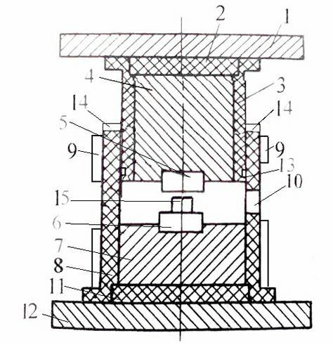
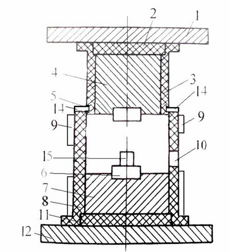
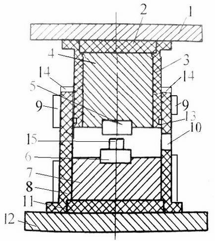
[0011] like figure 1 Shown is the structural representation of the present invention, and it comprises upper support plate 1, upper insulation board 2, upper cover 3, upper mold frame 4, upper mold 5, lower mold 6, lower mold frame 7, lower cover 8, inductor 9, hole 10, lower insulation board 11 and lower support board 12.
[0012] Described lower mold 6 is provided with blank 15, and upper mold 5 and lower mold 6 are respectively fixed on upper mold frame 4 and lower mold frame 7, and the outer side of upper mold frame 4 and lower mold frame 7 is respectively provided with upper cover 3 And the lower sleeve 8, the upper mold frame 4 is connected with the upper support plate 1 through the upper heat insulation plate 2, the lower mold frame 7 is connected with the lower support plate 12 through the lower heat insulation plate 11, and the axial end surface of the lower sleeve 8 is ...
PUM
 Abstract
Description
Claims
Application Information