

Matching structure of combined mold and punching machine for manufacturing flexible circuit board
A flexible circuit board and combined mold technology, applied in metal processing and other directions, can solve the problems that have not been seen and can be compensated, and achieve the effect of improving mold changing efficiency, reducing work intensity, and ensuring convenience.
- Summary
- Abstract
- Description
- Claims
- Application Information
AI Technical Summary
Problems solved by technology
Method used
Image

Examples
Embodiment
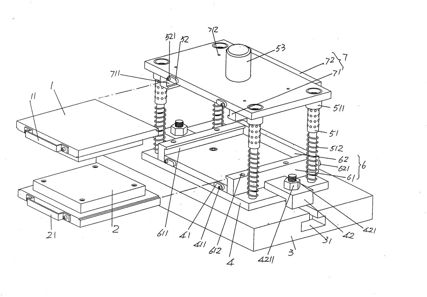
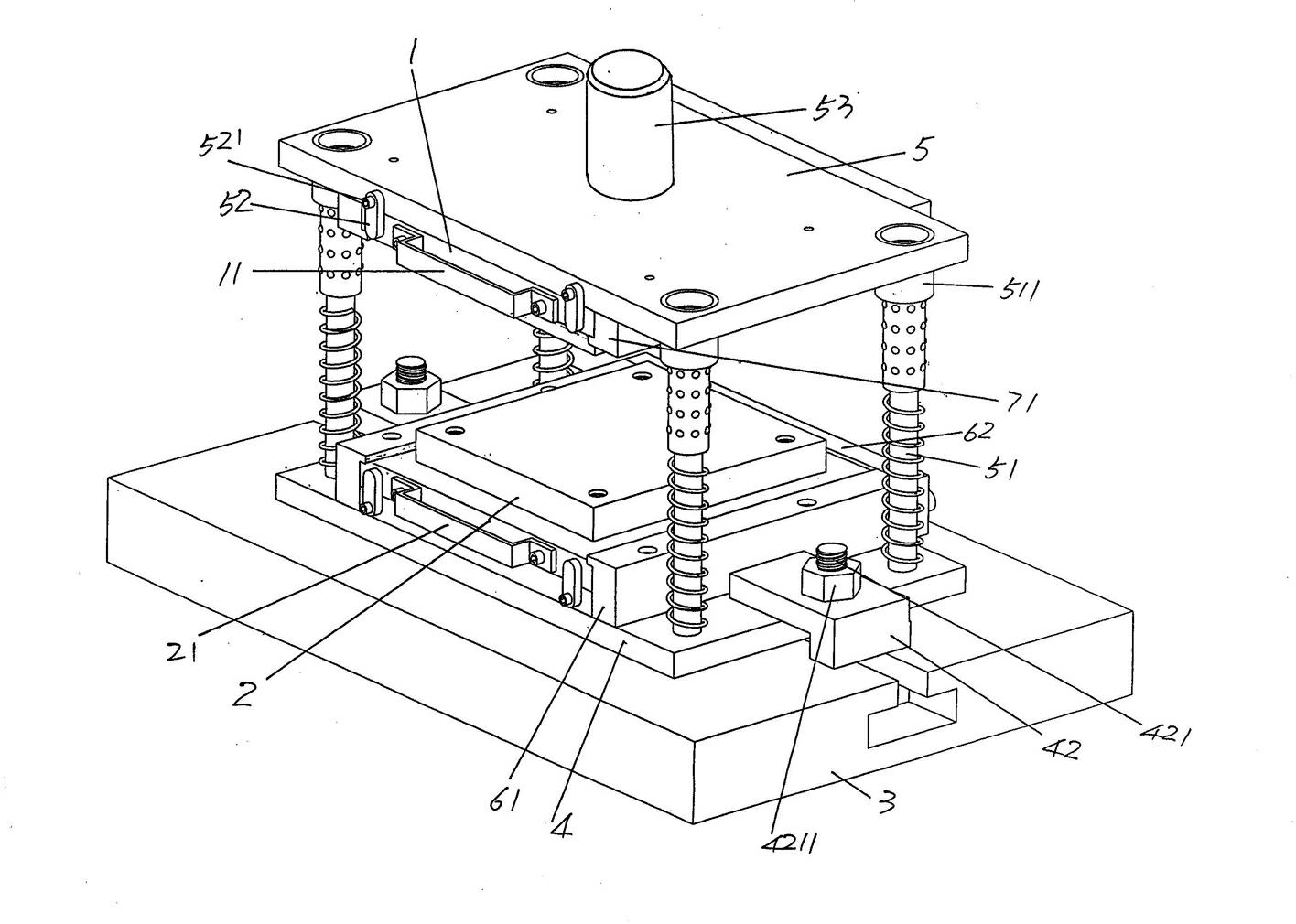
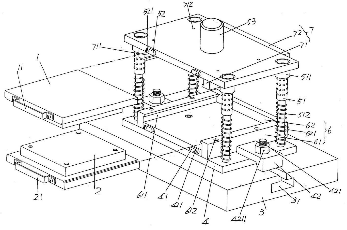
[0021] See figure 1 , the upper mold 1 and the lower mold 2 are given. On the end surface of the outward end of the upper mold 1 when it is in use, there is fixed an upper mold handle 11 whose structure is not limited by the illustration, and when the lower mold 2 is in use A lower mold handle 21 whose structural form is not restricted by the drawing is fixed on the end face of the end facing outward. The upper and lower mold handles 11, 21 are a handle or a pull-tab structure in this embodiment, but they can also be pinches in the shape of gourd heads.
[0022] The press platform 3, the upper mold frame 5 and the lower mold frame 4 of the punching machine are given. On the press platform 3 and located in the center of the width direction, there is a screw penetrating from one end of the press platform 3 to the other end. The moving groove 31, the cross-sectional shape of the screw moving groove 31 is T-shape of English letters, more precisely, it is T-shape inverted 180...
PUM
 Abstract
Description
Claims
Application Information