
Novel high-strength constant-resistance large deformation anchor rod and using method thereof

A technology of constant resistance, large deformation, and anchor rods, which is applied in the installation of anchor rods, earthwork drilling, sheet pile walls, etc., can solve the problems of pipe body cracking, unstable performance, and insufficient resistance, etc., and achieve stable performance and simple structure , the effect of increasing strength

Inactive Publication Date: 2014-11-12
SHANDONG UNIV OF SCI & TECH
View PDF8 Cites 4 Cited by
  • Summary
  • Abstract
  • Description
  • Claims
  • Application Information

AI Technical Summary

Problems solved by technology

The allowable deformation of the above-mentioned devices is generally small and cannot adapt to the characteristics of large deformation. However, the device with a large allowable deformation can provide insufficient effective resistance and unstable performance, and cannot meet the support needs of modern underground engineering.
For example, the patent CN 201943725U has the problems of insufficient resistance and complicated structure
Patent CN 101858225A, in the process of deformation of its constant resistance device, the outer tube expands under pressure in the circumferential direction, causing damage to the anchoring agent, and the tube body is prone to cracking, resulting in failure of the anchor rod and safety accidents, so it is difficult to spread application

Method used


Image

  • Novel high-strength constant-resistance large deformation anchor rod and using method thereof
  • Novel high-strength constant-resistance large deformation anchor rod and using method thereof
  • Novel high-strength constant-resistance large deformation anchor rod and using method thereof

Examples


Embodiment 1

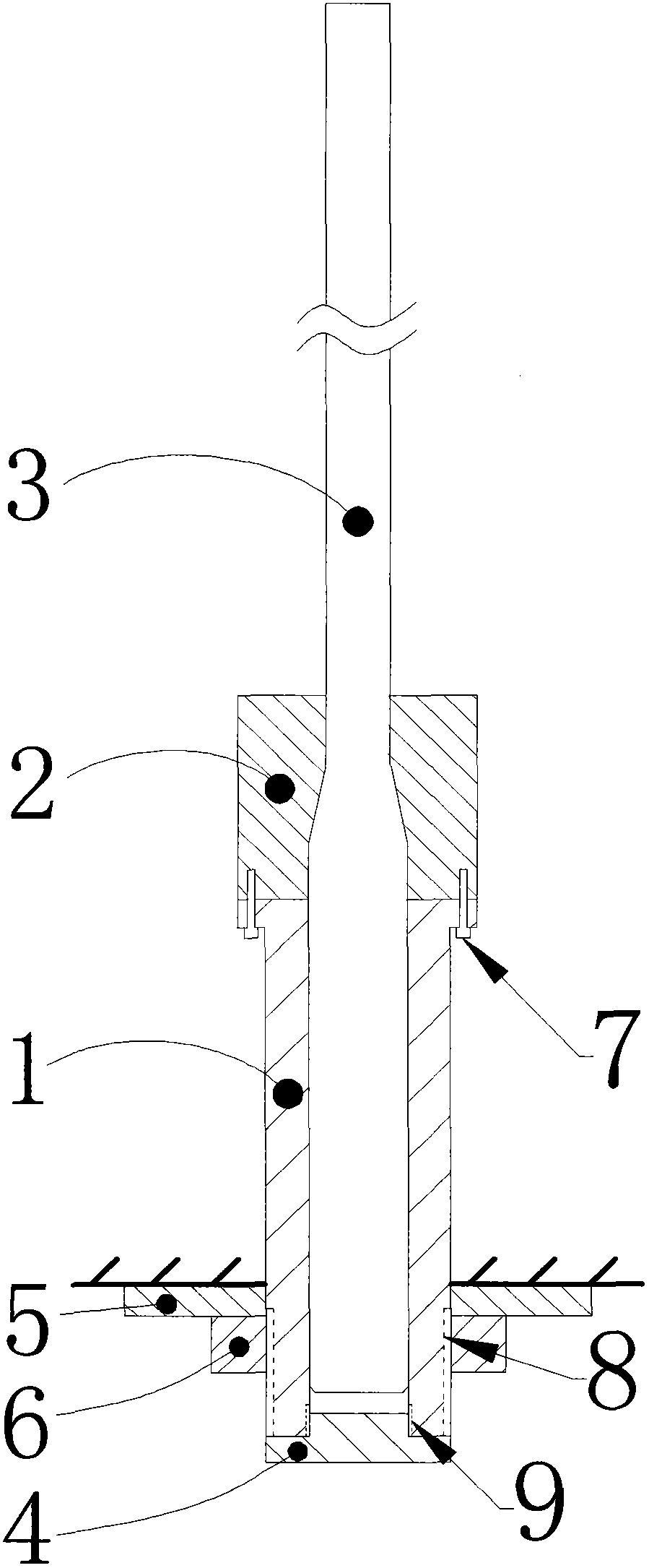
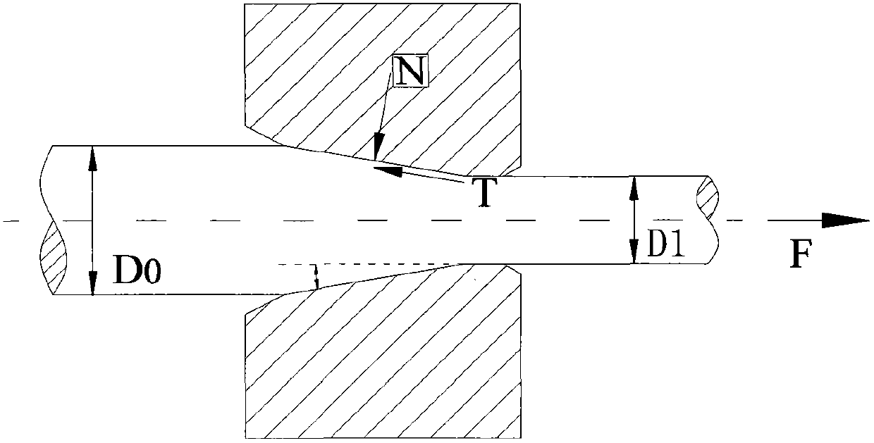
[0041] combine figure 1 , a new type of high-strength, constant-resistance, and large-deformation bolt, which includes a bolt body, a nut 6 and a tray 5, wherein the bolt body includes: a cold-drawn rod body 3, a sleeve 1 and a wire drawing die 2; a cold-drawn rod body 3 The diameter of the section at the rear end is larger than the diameter of the front rod body, that is, one end is a thick section, the other end is a thin section, and the gap between the thick section and the thin section is a tapered section; ; The wire drawing die 2 is a tapered die, the taper of the wire drawing die 2 matches the taper of the cold drawn rod 3 tapered section, and the rear end of the casing 1 is provided with an external thread 8 for installing a nut.

[0042] The above casing 1 is a cylindrical steel pipe, its diameter and wall thickness should meet the anchoring force requirements, and its length should meet the deformation of the designed anchor rod;

[0043] The material of the above-...

Embodiment 2

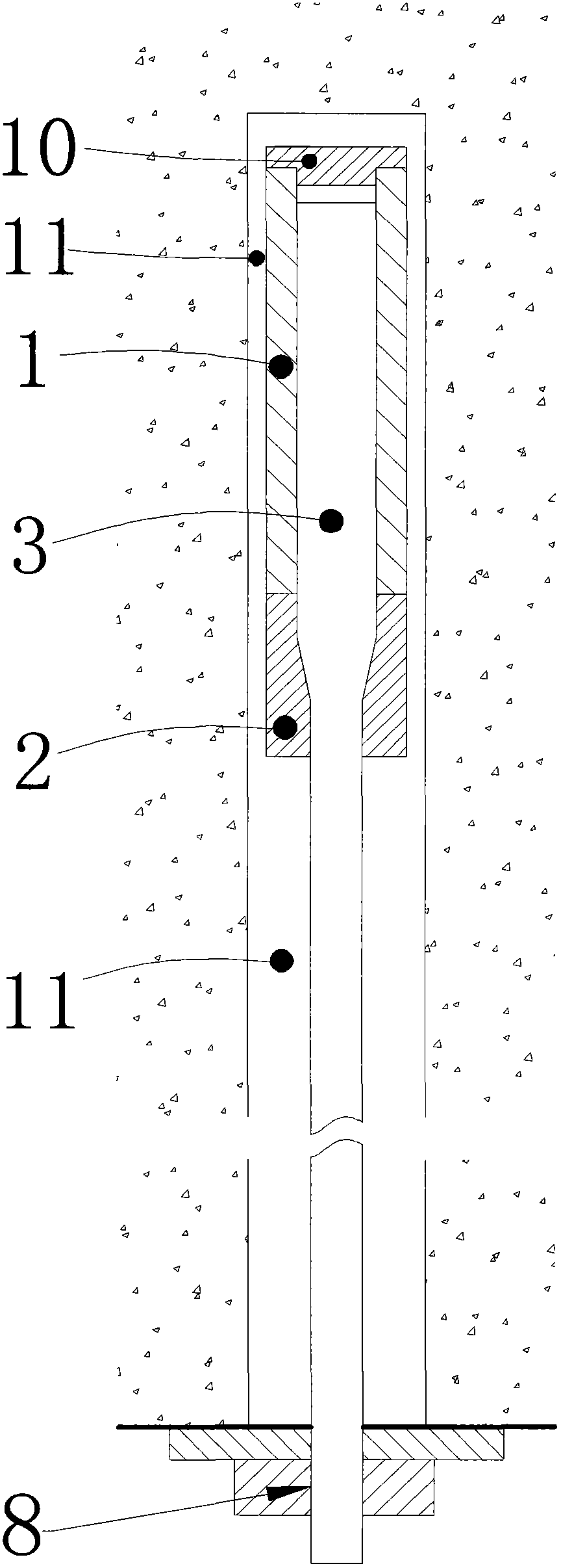
[0053] combine image 3 , a new type of high-strength, constant-resistance, and large-deformation bolt, which is compatible with figure 1 The technical solutions shown are basically the same, and will not be described again here. The main difference is that the thin section of the cold-drawn rod body 3 has a smooth surface, and the end of the cold-drawn rod body 3 is provided with an external thread 8 for installing the nut 6; Processed with ribs to increase the friction between it and the anchoring agent.

[0054] The usage method of embodiment two is:

[0055] Step 1: Drill the anchor hole in the support roadway, the diameter of the anchor hole matches the diameter of casing 1;

[0056] Step 2: install the casing 1 in the anchor hole towards the bottom of the hole, inject the anchoring agent 11 into the anchor hole, and after the anchoring agent 11 is solidified, put the tray 5 on the outcrop of the cold-drawn rod body 3, tighten the nut 6, and reach Design preload.

Embodiment 3

[0058] combine Figure 4 , a new type of high-strength, constant-resistance, and large-deformation bolt, which is compatible with figure 1 The technical solutions shown are basically the same, and will not be described again here. The main difference is that the thick section and the tapered section of the cold-drawn rod body 3 adopt a hollow structure, and the thin section adopts a solid structure. As the drawing limit of the rod body; the two adopt threaded connection or welding structure.

[0059] In all the above-mentioned embodiments, the casing 1 is a cylindrical steel pipe, its diameter and wall thickness should meet the anchoring force requirements, and its length corresponds to the length of the thick section of the cold-drawn rod body; the casing 1 and the wire drawing die 2 are connected, except for using In addition to the high-strength bolt 7, the available methods also include threaded connection or welding.


PUM


Abstract

The invention discloses a novel high-strength constant-resistance large deformation anchor rod and a using method thereof. An anchor rod body of the novel high-strength constant-resistance large deformation anchor rod comprises a cold-drawn rod body, a cylindrical sleeve and a wire drawing mold, wherein the diameter of one end of the cold-drawn rod body is greater than that of the other end, namely one thick section and one thin section; a cone-shaped section is formed between the thick section and the thin section; the surface of the thin section is provided with rib patterns; the cylindrical sleeve is connected with the wire drawing mold and is sleeved on the cold-drawn rod body; the wire drawing mold is a cone-shaped mold; the taper of the wire drawing mold is matched with the taper of the cone-shaped section; and the end head of the cylindrical sleeve or the end head of the cold-drawn rod body is provided with external threads for installing nuts. The anchor rod can stretch under stress and is not damaged when surrounding rock is subjected to large deformation, and the cold-drawn rod body has large displacement to adapt to deformation of the surrounding rock.

Description

technical field [0001] The invention relates to a support bolt used in underground projects such as water conservancy and hydropower projects, tunnel projects, and mine projects, and in particular to a constant-resistance high-strength bolt capable of continuous deformation without damage. Background technique [0002] In the support of underground projects such as water conservancy and hydropower projects, tunnel projects, and mining projects, bolts are a kind of support equipment that is widely used. With the continuous increase of mining depth and the construction of large-scale underground engineering, the geological conditions are becoming more and more complex, and the surrounding rock often shows the characteristics of large deformation. When the deformation of the surrounding rock is large and exceeds the range that the bolt can bear, it will lead to the failure of the bolt, and then cause the instability and destruction of the underground engineering. In this case,...

Claims


Application Information

Patent Timeline
Patent Type & Authority Patents(China)
IPC IPC(8): E21D21/00E02D5/74
Inventor 王刚吴学震蒋宇静乔卫国
Owner SHANDONG UNIV OF SCI & TECH
Learn More