Tubular curtain type radiation ceiling air conditioner tail end device

A radiant ceiling and air-conditioning terminal technology, which is applied in the field of air-conditioning terminal devices, can solve the problems of uneven temperature field distribution on the panel surface, easy condensation, condensation on the radiation surface, etc., and achieve guaranteed cold and heat radiation performance and anti-condensation The effect of strong ability and long service life

Inactive Publication Date: 2012-09-19
HUNAN UNIV
9 Cites 1 Cited by

AI-Extracted Technical Summary

Problems solved by technology

But there are still the following two problems: 1. The heat conduction efficiency between materials is low. Cold and heat need to be transferred from the pipe wall and filled with heat-conducting materials to the plate. Increasing the transfer medium will inevitably increase the heat loss, and the overall thermal efficiency is still relatively low. Low; 2. During cooling, condensation is prone to occur on the radiation surface, and the temperature field distribution on the surface of the panel is uneven. The temperature on the contact line between the pipe and the panel is the lowest, and condens...

Abstract

The invention discloses a tubular curtain type radiation ceiling air conditioner tail end device comprising a tubular section bar, wherein the internal space of the tubular section bar is divided by a lower layer dividing wall and an upper layer dividing wall, the hollow cavity between the lower layer dividing wall and the bottom part of the tubular section bar is a water passage cavity, the hollow cavity between the lower layer dividing wall and the upper layer dividing wall is a heat insulation air dividing layer, the hollow cavity between the upper layer dividing wall and the top part of the tubular section bar is an open neck, a connecting head is screwed with a connecting hose pipe, the connecting hose comprises a connecting hose I and a connecting hose II, the end part of the connecting hose I is screwed with a connecting opening on a water supply pipe, the connecting hose II is screwed with a connecting opening on a water return pipe, the tubular section bar, a pipe end sealing cover, the connecting head, the connecting hose, the water supply pipe and the water return pipe are connected together to form a closed cold and hot water flow channel, the middle part of a hook is connected with a buckle on the open neck, the upper part of the hook is fixedly connected with a keel, and a suspender is fixedly connected with the keel through a hoisting hole. The tubular curtain type radiation ceiling air conditioner tail end device disclosed by the invention has a simple and compact structure, convenience in installation, flexibility in operation, high heat efficiency, strong dew formation resistance, extensive application range and long service life.

Application Domain

Lighting and heating apparatusAir conditioning systems

Technology Topic

Water pipeEngineering +4

Image

  • Tubular curtain type radiation ceiling air conditioner tail end device
  • Tubular curtain type radiation ceiling air conditioner tail end device
  • Tubular curtain type radiation ceiling air conditioner tail end device

Examples

  • Experimental program(2)

Example Embodiment

[0039] Example 1
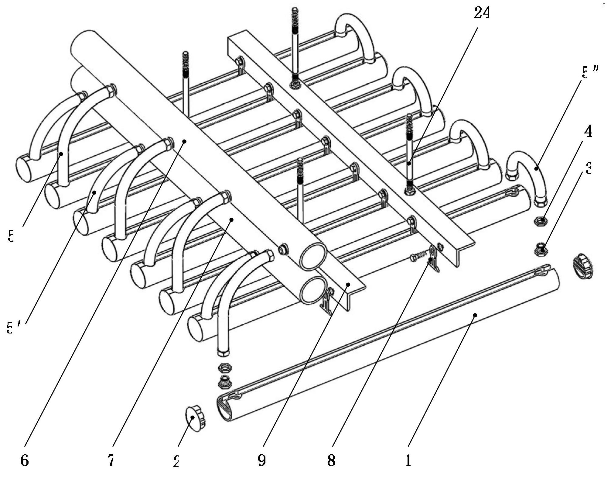
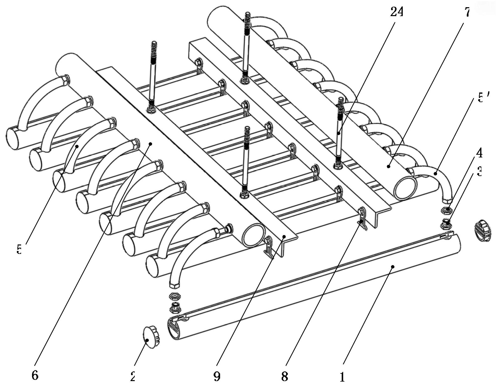
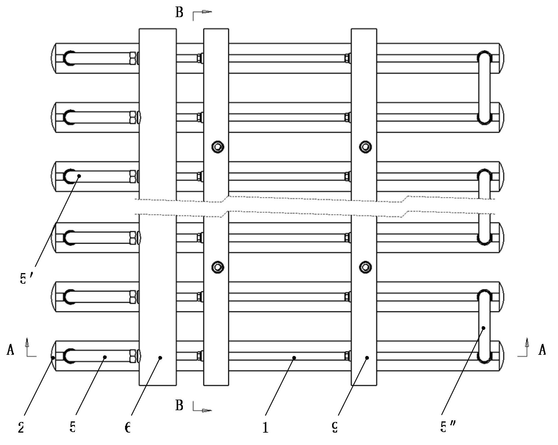
[0040] Reference Figure 1a , 2a , 3a, 4, 5a, 6, this embodiment includes eight tubular profiles 1. The internal space of the tubular profile 1 in the axial extension direction is separated by a lower partition wall 10 and an upper partition wall 11, between the lower partition wall 10 and the bottom of the tubular profile 1 The cavity of is the water-passing cavity 12, the cavity between the lower partition wall 10 and the upper partition wall 11 is the thermal insulation air partition 13, and the cavity between the upper partition wall 11 and the top of the tubular profile 1 is an open card slot 14. The lower partition wall 10 located at the ends of the two ends of the tubular profile 1 is provided with connecting holes, and the upper partition wall 11 is provided with a vertical relief hole. The connector 3 passes through the connecting hole from bottom to top and is screwed with the connecting hose. , And fastened by the lock nut 4, the pipe end cap 2 is fixedly connected to the tubular profile 1. The connecting hose includes a connecting hose I5 and a connecting hose II 5', and the end of the connecting hose I5 is connected to the water supply pipe 6. The connecting port of the connecting hose Ⅱ 5'is screwed to the connecting port on the return pipe 7. The tubular profile 1, the pipe end cap 2, the connector 3, the connecting hose, the water supply pipe 6, and the return pipe 7 are connected to form a closed The middle part of the hook 8 is connected with the buckle on the open slot 14, the upper part of the hook 8 is provided with height adjustment holes, the two wings of the keel 9 are respectively provided with positioning holes and lifting holes, and the upper part of the hook 8 passes through the height adjustment holes and The positioning hole is fixedly connected to the keel 9, and the boom 24 is fixedly connected to the keel 9 through the lifting hole.
[0041] The water supply pipe 6 and the water return pipe 7 are located at the same end of the tubular profile 1; and the other ends of the tubular profiles 1 are connected by a connecting hose III 5″.
[0042] The tube end cover 2 is fixedly connected to the tubular profile 1 by welding or hot melt.
[0043] The tubular profile 1 is a plastic steel profile.
[0044] The cross-sectional profile of the tubular profile 1 is circular.
[0045] A protrusion is provided on one side of the pipe end cover 2 connected with the tubular profile 1, and the profile of the protrusion is consistent with the cross-sectional inner profile of the tubular profile 1.
[0046] The outer surface of the tubular profile 1 and the outer surface of the pipe end cover 2 are provided with a decorative coating and a hydrophobic material coating in sequence from the inside to the outside.
[0047] The connecting hole on the lower partition wall 10 and the relief hole on the upper partition wall 11 are aligned with the central axis.
[0048] The aperture of the relief hole is larger than the circumscribed diameter of the outer contour of the lock nut 4.
[0049] When in use, the end device of the tube curtain type radiant ceiling air conditioner of the present invention can be horizontally hoisted under the roof, beams and other building components through the suspension rod 24.

Example Embodiment

[0050] Example 2
[0051] Reference Figure 1b , 2b , 3b, and 5b. The difference between this embodiment and Embodiment 1 is that the water supply pipe 6 and the water return pipe 7 are located at the left and right ends of the tubular profile 1 respectively. The tubular profile 1 is an aluminum profile. The rest is the same as in Example 1.
[0052] In the above-mentioned embodiment, the shape, material and connection mode of each component can be changed. For example, the cross-sectional shape of the tubular profile 1 can be changed, including circular, elliptical or polygonal shapes (see Figure 7a , 7b , 7c, 7d, 7e, 7f); The overall size of the tube curtain type radiant ceiling air-conditioning terminal device of the present invention changes with the ceiling space; the material selection of each component can also be changed.
[0053] By using the present invention, some problems or contradictions existing in the arrangement of the existing hanging piece, square or round ceiling and the terminal device of the air conditioning system are overcome. The idea is not limited to the panel radiant air conditioner, which effectively overcomes the existing radiant central There are many defects in the terminal equipment of the air conditioning system. The invention has high thermal efficiency, better anti-condensation ability, simple on-site installation, and guaranteed cold and heat radiation performance.

PUM

no PUM

Description & Claims & Application Information

We can also present the details of the Description, Claims and Application information to help users get a comprehensive understanding of the technical details of the patent, such as background art, summary of invention, brief description of drawings, description of embodiments, and other original content. On the other hand, users can also determine the specific scope of protection of the technology through the list of claims; as well as understand the changes in the life cycle of the technology with the presentation of the patent timeline. Login to view more.

Similar technology patents

Body condition measuring device

InactiveUS20050234351A1simple structure
Owner:DENSO CORP

Magnetic cooling apparatus and control method thereof

ActiveUS20130180263A1simple structure
Owner:SAMSUNG ELECTRONICS CO LTD

Dual-Drivetrain of Power-Assist Vehicle

InactiveUS20100181130A1enhance uphill momentumsimple structure
Owner:CHOU WEN CHENG

Classification and recommendation of technical efficacy words

  • Simple structure
  • Easy to install

Sharing system for air-conditioning coat

InactiveCN107440179ASimple structureeasy to wear
Owner:QINGDAO HAIER AIR CONDITIONER GENERAL CORP LTD

Feeding device of sorter of batteries plate

InactiveCN101357717ASimple structurecooperate well
Owner:NANJING NORMAL UNIVERSITY

Emergency parachuting device and method for multiple-rotor unmanned aerial vehicle

InactiveCN103895870Aavoid aircraft crashSimple structure
Owner:SOUTH CHINA AGRI UNIV +1

Cooking electric appliance

PendingCN107647763AEasy to installAvoid insulation loss
Owner:FOSHAN SHUNDE MIDEA ELECTRICAL HEATING APPLIANCES MFG CO LTD

System for monitoring vibration of rotating machinery rolling bearing in wireless mode

InactiveCN102053016Ameasurementanalysisdatareal-timeEasy to install
Owner:JIANGSU UNIV
Why Eureka
Try Eureka