Regeneration system of dehumidifying solution for moist air

A technology of solution regeneration and humid air, which is applied in the field of humid air dehumidification, can solve problems such as impracticability and difficulty in solution regeneration, and achieve the effects of improving regeneration efficiency, obvious energy saving effect, and efficient utilization

CN102679468AInactive Publication Date: 2012-09-19HENAN UNIV OF SCI & TECH
9 Cites 12 Cited by

Patent Information

Authority / Receiving Office
CN · China
Patent Type
Applications(China)
Current Assignee / Owner
Publication Date
2012-09-19
Estimated Expiration
Not applicable · inactive patent

Smart Images

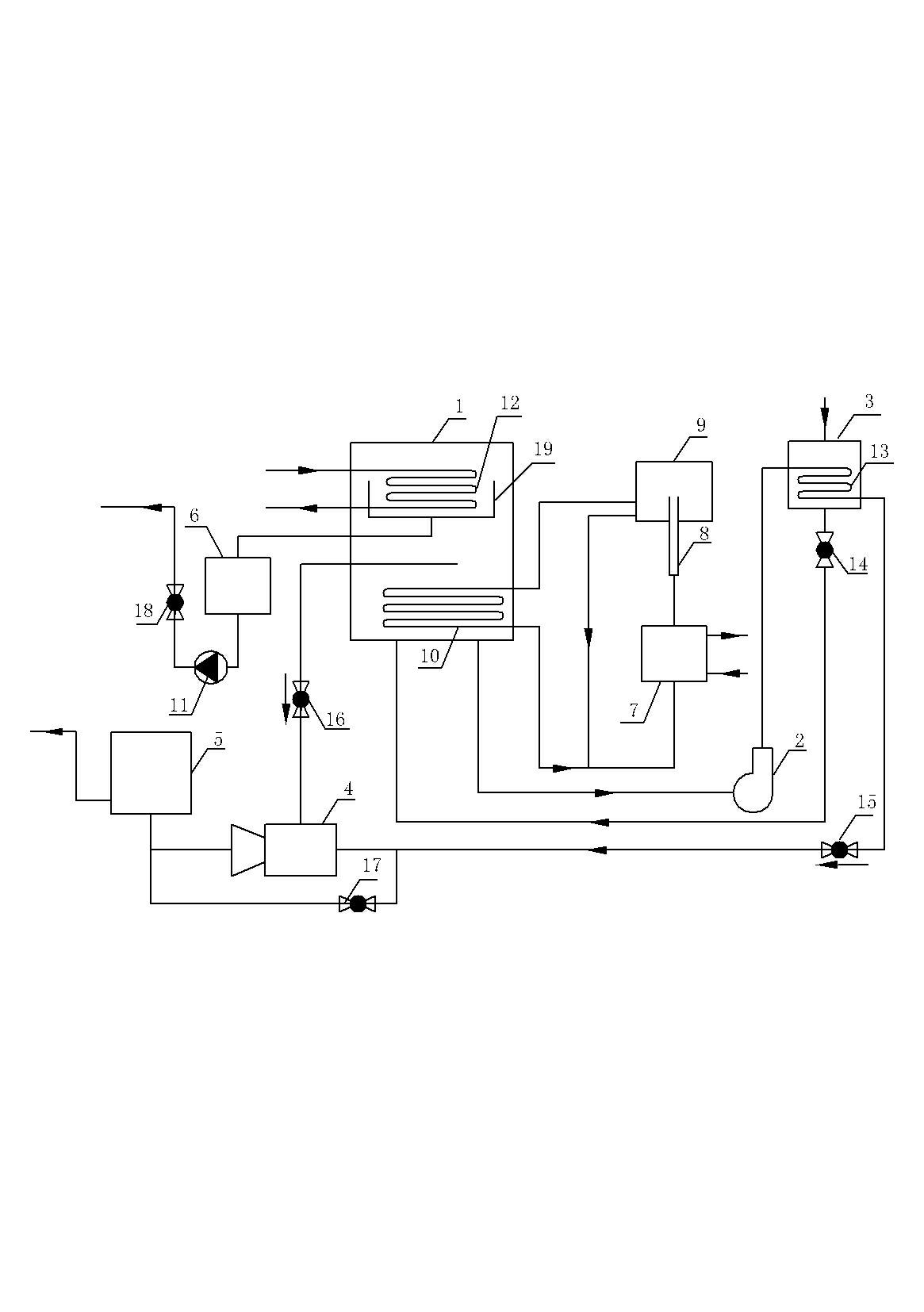
  • Figure 1
    Figure 1
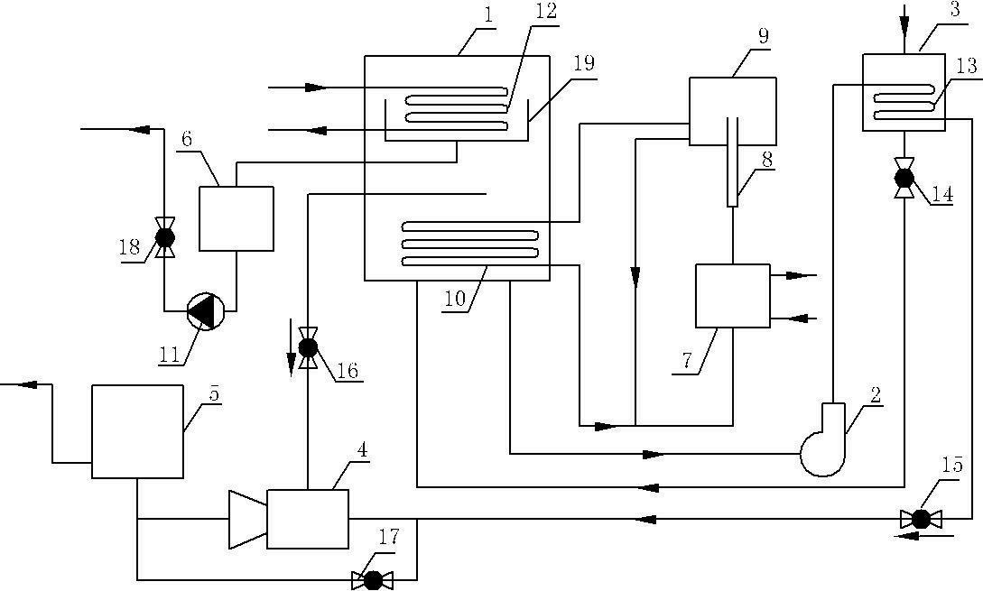
  • Figure 2
    Figure 2
Patent Text Reader

Abstract

The invention relates to a regeneration system of a dehumidifying solution for moist air, wherein a generator is internally provided with a heating coil and a condensing coil, and the condensing coil is in a condensing disc provided with a condensate outlet. A liquid outlet of a dilute solution storage tank is connected with a liquid inlet of the generator, and a liquid outlet of the generator is connected with an inlet of a solution heat exchange tube through a solution pump. An outlet of the solution heat exchange tube is divided into two paths, and one solution heat exchange tube is connected with a dehumidifying device through a flow adjusting valve while the other solution heat exchange tube is connected with a work liquid inlet of an ejector. A driven fluid inlet of the ejector is communicated with a gas outlet of the generator and an outlet of the ejector is connected with a liquid inlet of the dehumidifying device after being joined with an outlet of the flow adjusting valve. An outlet of the heating coil is connected with an inlet of a heater, an outlet of the heater is connected with a vapor-liquid separator through a bubble pump, a gas outlet of the vapor-liquid separator is connected with an inlet of the heating coil, and a liquid outlet of the vapor-liquid separator is connected with the inlet of the heater after being joined with the outlet of the heating coil.
Need to check novelty before this filing date? Find Prior Art

Description

technical field

[0001] The invention relates to a regeneration system of a dehumidification solution for dehumidification of humid air, belonging to the technical field of humid air dehumidification. Background technique

[0002] At present, the most widely used solution dehumidifiers are LiBr, LiCl and CaCl. 2 and other solutions, while using CaCl 2 It is relatively rare for the solution to dehumidify alone. Regeneration is a central issue in this technology for dehumidification using highly hygroscopic solutions. The dehumidification and solution regeneration efficiency of solution dehumidifiers have always been the focus of research. Using waste heat as a heat source for solution regeneration has energy-saving significance. For example, the condensation heat of air-conditioning units used is used as a heat source for solution regeneration. Control the air-conditioning system, the system recovers the heat dissipation of the condenser of the air source heat pump unit, an...

Examples

Embodiment Construction

[0015] An embodiment of a wet air dehumidification solution regeneration system, in figure 1 Among them, the dilute solution storage tank 3 of the wet air dehumidification solution regeneration system is provided with a solution heat exchange tube 13, and the generator 1 is provided with a heating coil 10 and a condensation coil 12, and the heating coil 10 is located in the generator 1 In the lower part, the condensation coil 12 is located on the upper part of the generator 1 . A condensate pan 19 is also fixed inside the generator 1, and the condensate coil 12 is located in the condensate pan 19. A condensate discharge port is provided on the condensate pan 19, and a condensate storage tank is connected to the condensate discharge port. 6. The outlet of the condensate storage tank 6 is connected to the inlet of the condensate pump 11 , and the outlet of the condensate pump 11 discharges the condensate through the second switch control valve 18 . The liquid inlet of the dilut...