
Quickly assembled hanging part with low flow resistance for heat exchange tube

A heat exchange tube, low flow resistance technology, applied in the direction of cleaning heat transfer devices, heat transfer modification, heat exchange equipment, etc., can solve the problems of large inlet pressure loss of heat exchange tubes, increased pipeline transportation resistance, blocked pipelines, etc. Achieve the effect of facilitating quick installation, ensuring stability and reducing resistance loss

Active Publication Date: 2013-07-03
BEIJING UNIV OF CHEM TECH
View PDF3 Cites 0 Cited by
  • Summary
  • Abstract
  • Description
  • Claims
  • Application Information

AI Technical Summary

Problems solved by technology

[0002] With the continuous progress of society in the 21st century, energy saving and emission reduction in today's society is a key technology that the world attaches great importance to, especially in petroleum, chemical, thermal power, nuclear power, metallurgy, light industry, aviation devices and ship vehicles, etc. Many heat exchangers are applied in many fields, among which the shell-and-tube heat exchanger is the most widely used, but the inner wall of these heat exchange tubes generally has layered dirt, which leads to an increase in the resistance of fluid transport in the pipeline, and in severe cases It will block the pipe, and the heat transfer performance will be greatly reduced at the same time; the dirt in the heat exchange tube will seriously reduce the heat transfer efficiency and cause major energy waste. At the same time, the dirt is generally corrosive, and the pipe wall will be corroded.
The pendant is a flow-guiding self-supporting pendant. The Chinese patent application number is 201010184095.9. It mainly includes a hollow shaft, a connecting rod, a support platform and an extension end. The hollow shaft, the support platform and the extension end are three with inner holes. The concentric cylinder can well ensure the alignment of the flexible shaft, but the disadvantage is that when the pendant is installed at the inlet of the heat exchange tube, the resistance loss is relatively large, and when it is installed at the water outlet, it will block the sundries in the heat exchange tube At the outlet, so that it is blocked; in order to solve the problem of large pressure loss at the inlet of the heat exchange tube, Chinese patent application number 201110097258.4, the name of the invention is "link type pendant in the heat exchange tube", which mainly includes a link and a matching sleeve, a link It is composed of a bond blade and a central shaft hole, and the matching sleeve is composed of a long circular sleeve, a short circular sleeve and a groove, which effectively reduces the pressure loss at the inlet of the heat exchange tube and increases the disturbance of the fluid, but the actual When the power plant is installed, it needs to be installed quickly. Before installation, it is necessary to weld the limit piece of the water inlet, then insert the combined rotor into the heat exchange tube from the water outlet, and finally install the water inlet pendant, but the existing water inlet pendant of the heat exchange tube cannot meet the requirements. this request

Method used


Image

  • Quickly assembled hanging part with low flow resistance for heat exchange tube
  • Quickly assembled hanging part with low flow resistance for heat exchange tube
  • Quickly assembled hanging part with low flow resistance for heat exchange tube

Examples


Embodiment Construction

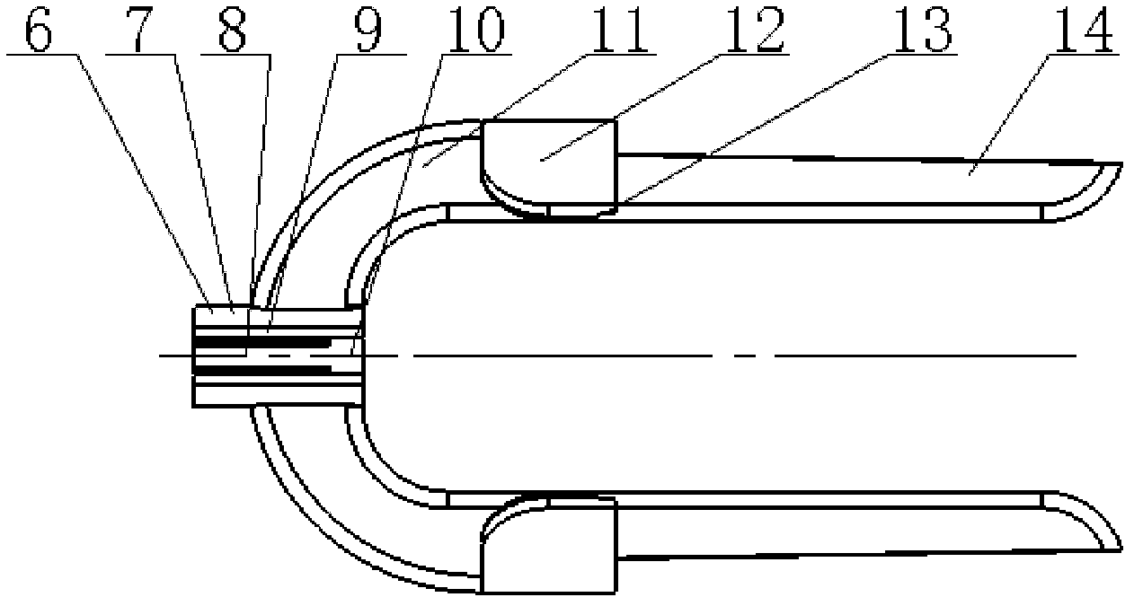
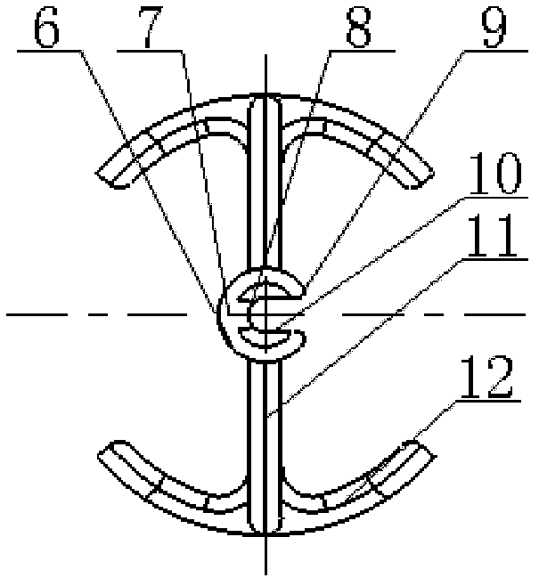
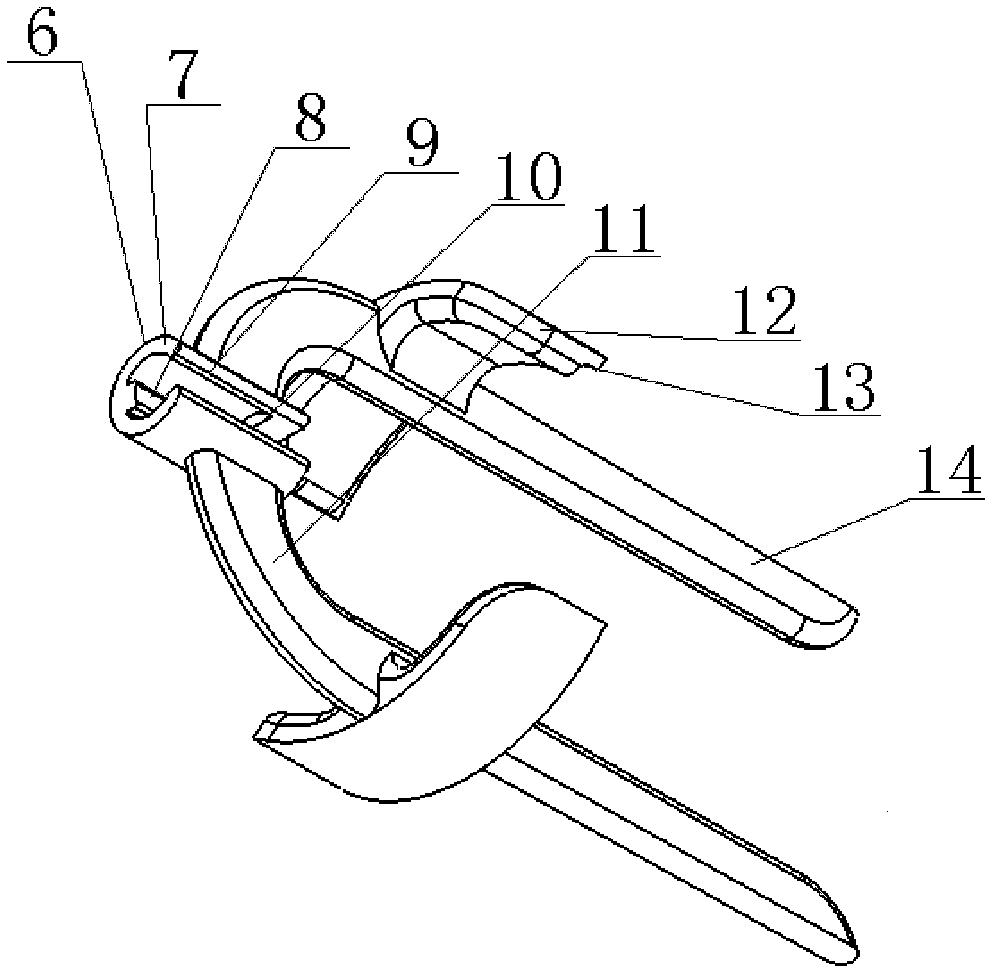
[0021] Such as Figure 6 and Figure 7 As shown, an implementation example of a low-flow-resistance quick-installation hanger for heat exchange tubes involved in the present invention includes a support shaft 1, a stopper 2, a sleeve 3, a hanger body 6, and a rotor 15. The sleeve The tube 3 and the pendant body 6 are mounted on the support shaft 1, and several rotors 15 are mounted on the support shaft 1, wherein the casing 3 and the pendant body 6 together form a low-flow-resistance quick-installation pendant for the heat exchange tube, and the pendant body 6 includes a hollow shaft 7, a connecting rod 11, a support platform 12 and an extension end 14, and the left end of the casing 3 is equipped with a stopper 2.

[0022] Such as Figure 1 to Figure 8 , figure 1 It is the front view of the low-flow-resistance quick-installation pendant body of the heat exchange tube, figure 2 for figure 1 left view of image 3 yes figure 1 3D view, Figure 4 is the front view of the...


PUM


Abstract

The invention provides a quickly assembled hanging part with low flow resistance for a heat exchange tube. The quickly assembled hanging part is composed of a hanging part body and a sleeve, wherein the hanging part body comprises a hollow shaft, a connecting rod, a supporting platform and an extending end; the connecting rod is connected with the hollow shaft and the supporting platform; the supporting platform, the axis of the hollow shaft and the center of the connecting rod are coaxial with each other; the extending end is an extending part formed by a mode that the connecting rod passes through the supporting platform; the extending end is inserted into the heat exchange tube; the connecting rod of the hanging part has an arc-shaped structure; the connecting rod and the central area of the extending end are hollow; a distance is arranged between a solid part of the connecting rod and an inlet of the heat exchange tube; a sleeve boss and a sleeve slot are respectively matched witha hollow shaft slot and a hollow shaft boss; a small-diameter cylindrical section of the sleeve is inserted into a hole of the hollow shaft along the axis of the sleeve; the hollow shaft and the sleeve jointly ensure that a supporting shaft is located at the center of the heat exchange tube all the time; a blocking platform is arranged at the tail end of the hollow shaft of the hanging part; the inner diameter of the opening is as same as the inner diameter of the sleeve; and under the condition that the supporting shaft can pass through the hanging part, the sleeve is effectively prevented from dropping from the tail end of a central shaft of the hanging part, and the mounting is quick and convenient.

Description

technical field [0001] The invention relates to a support element for an interpolation element used for strengthening heat transfer and anti-fouling and decontamination at the water inlet end of a heat exchange tube in a shell-and-tube heat exchanger, a heat exchange reactor, and the like. Background technique [0002] With the continuous progress of society in the 21st century, energy saving and emission reduction in today's society is a key technology that the world attaches great importance to, especially in petroleum, chemical, thermal power, nuclear power, metallurgy, light industry, aviation devices and ship vehicles, etc. Many heat exchangers are applied in many fields, among which the shell-and-tube heat exchanger is the most widely used, but the inner wall of these heat exchange tubes generally has layered dirt, which leads to an increase in the resistance of fluid transport in the pipeline, and in severe cases It will block the pipe, and the heat transfer performan...

Claims


Application Information

Patent Timeline
Patent Type & Authority Patents(China)
IPC IPC(8): F28G3/00F28G15/00F28F13/12
Inventor 阎华姜鹏丁玉梅张震杨卫民
Owner BEIJING UNIV OF CHEM TECH
Features
  • Generate Ideas
  • Intellectual Property
  • Life Sciences
  • Materials
  • Tech Scout
  • Unparalleled Data Quality
  • Higher Quality Content
  • 60% Fewer Hallucinations
Learn More