Light distribution measuring device and method for crop canopy

A crop canopy and measuring device technology, applied in measuring devices, photometry, optical radiation measurement, etc., can solve the problems of difficult adjustment of measuring positions, heavy point measuring instruments, and inability to attach, etc. Accurate, easy-to-adjust effects

Active Publication Date: 2012-09-19
BEIJING RES CENT FOR INFORMATION TECH & AGRI
3 Cites 12 Cited by

AI-Extracted Technical Summary

Problems solved by technology

[0005] However, the main defects of the above-mentioned light distribution measuring device are: the point measuring instrument is thick and heavy, and it is difficult to install it on the designated position of the plant leaves. Even if it is installed, it will cause the plant leaves to lose their natural shape and bring errors to the measurement; The disadvantage is that the measurement position is difficult to adjust, and the light intensity information at the specified position cannot be measured. SunS...

Method used

With reference to Fig. 1, in the present embodiment, light sensor is due to be placed on plant leaf surface, therefore, while ensuring measuring accuracy, reducing sensor weight is also key point, therefore, sensor adopts ISL29004 light sensor, and this sensor quality is less , and can ensure the high accuracy of the acquired data, but when measuring the light distribution in the field, it is easy to ...

Abstract

The invention discloses a light distribution measuring device and a method for crop canopy and relates to the technical field of light distribution measurement. The device comprises a bearing unit, a receiving unit and at least one light sensor, wherein the bearing unit comprises a supporting part and a bearing part which is the same as leaves of a to-be-measured plant in shape; the light sensors are arranged on the bearing part respectively and are connected in series sequentially; and one of the light sensors is connected with the receiving unit. According to the invention, the bearing par of the bearing unit, which is the same as the leaves of the to-be-measured plant in shape, is used for bearing the light sensor, so that the measuring position can be adjusted conveniently, the natural shape of the leaves of the plant is not damaged, and the precision of light distribution measuring is improved.

Application Domain

Technology Topic

Image

  • Light distribution measuring device and method for crop canopy
  • Light distribution measuring device and method for crop canopy
  • Light distribution measuring device and method for crop canopy

Examples

  • Experimental program(1)

Example Embodiment

[0039] Example
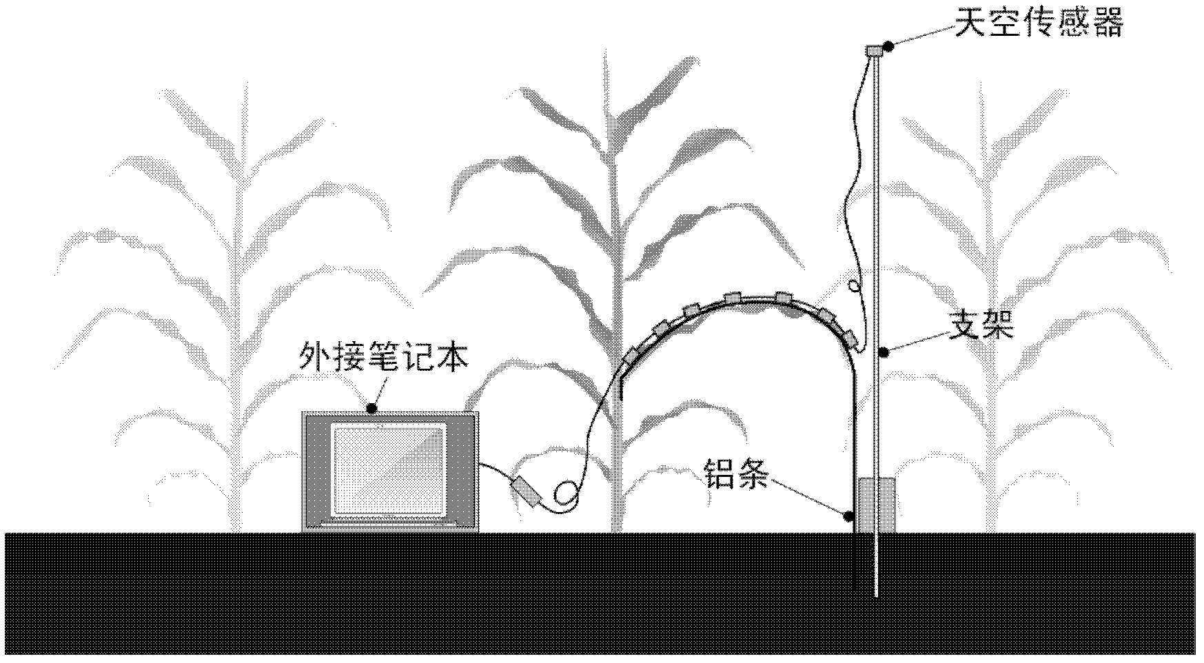
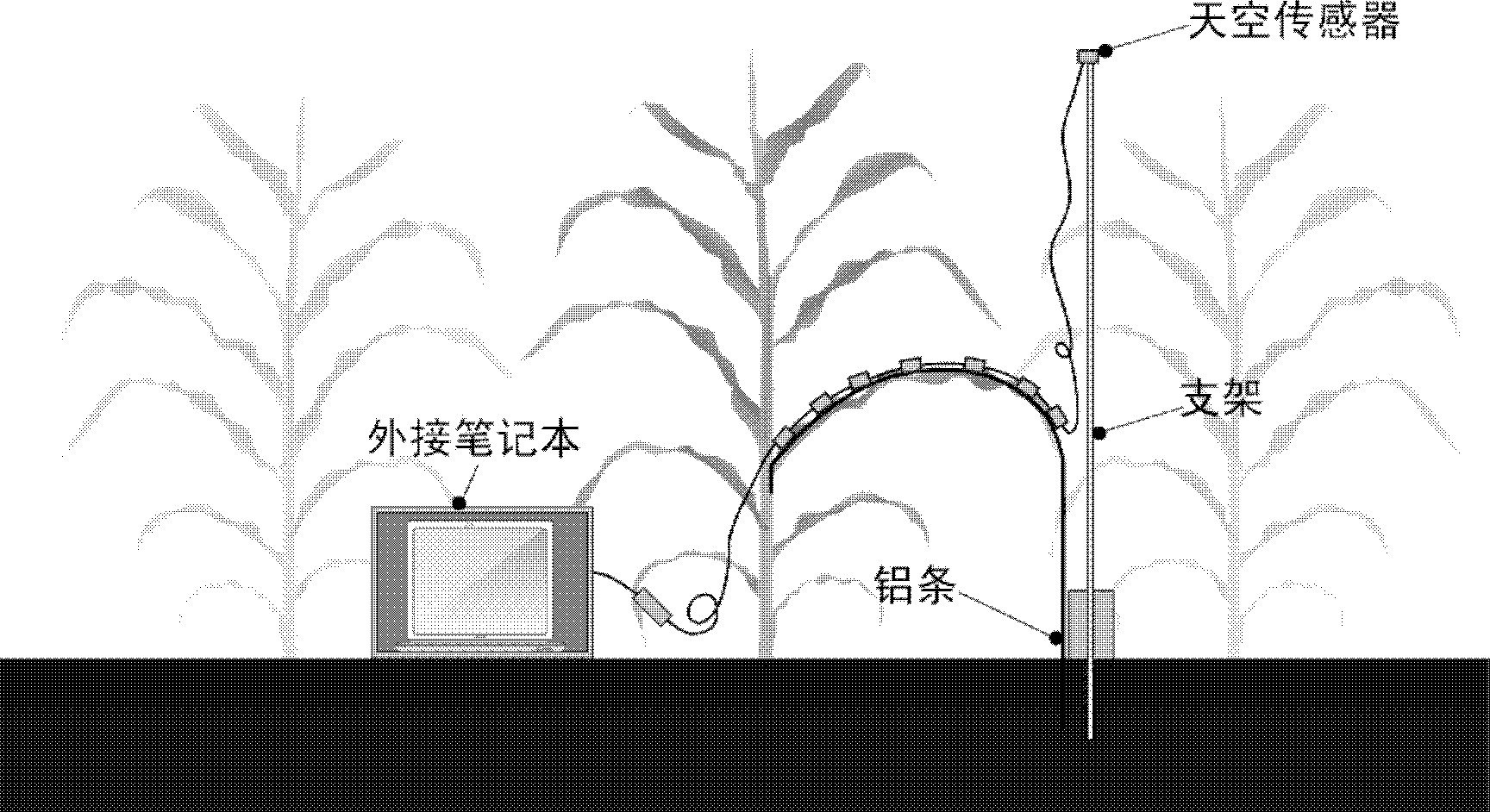
[0040] refer to figure 1 , in this embodiment, since the light sensor is to be placed on the surface of the plant leaf, it is also important to reduce the weight of the sensor while ensuring the measurement accuracy. It has high precision, but when measuring the light distribution in the field, it is easy to cause the light intensity to exceed the range. Therefore, a filter is added to the sensor. Because of the filter, it is necessary to measure the light intensity of different intensities The filter coefficient is determined to restore the collected signal to ensure that the system outputs the correct light intensity value. After measurement, the weight of a single sensor plus an optical filter is 11.90g.
[0041] Due to the limitation of data transmission, each line only allows 8 sensors, and each line is equipped with a notebook (receiving unit) to record data, and the sensors are connected by data lines with low quality, and the data lines are equipped with 15cm, 20cm and 30cm There are three lengths, the weight of the data line is 6.09g (15cm long data line) to choose in practical applications, and the data transmission protocol is the I2C bus protocol;
[0042] When measuring the crop leaves to be tested, the following steps are included:
[0043] According to the crop leaves to be measured, design the shape of the light frame and the way of fixing the frame: firstly, determine the main shape of the crop leaves for which the light distribution is to be measured. Taking corn as an example, select the corn leaves for which the light distribution is to be measured, and use a digitizer Measure the shape of its veins, select an aluminum strip of a certain length (that is, a metal strip with a weight of 0.3g/cm) to process it into a vein curve shape, the front end of the aluminum strip has 10cm to spare, and the rear end has about 80cm (according to the specific The distance between the tip of the crop blade and the ground is determined). The front end of the aluminum bar is inserted into the gap between the leaf sheath and the stem of the crop leaf to be tested and is bound and reinforced with a rope, and the rear end is inserted into the ground. The fixed aluminum bar is consistent with the shape of the leaf, and a light sensor can be placed on it. Multiple light sensors are evenly placed on the aluminum strip.
[0044] Design the measurement environment according to the specific crop growth environment: one end of the line needs to extend a sky sensor to the top of the canopy of the leaves of the crop to be measured to measure the light intensity outside the canopy, and the external sensor should be kept horizontal. The other end of each line is extended to the outside of the canopy and connected to the notebook through the data conversion port. Since the experiment needs to continuously observe the light distribution of the canopy, the notebook needs to be placed in a box to prevent excessive temperature caused by long-term sunlight exposure. There needs to be a certain distance from the measurement group to reduce the influence of the box on the light distribution of the canopy.
[0045] refer to figure 2 , Restoration of light intensity measurement data: The light intensity received by the light sensor is the light intensity filtered by the optical filter. In order to obtain the actual light intensity at the measurement position, the measured light intensity needs to be restored. Experiments have shown that the filter changes linearly for different intensities of light intensity, so the reduction formula is determined to be L=6600.0×Va, where Va is the actual measured value of the sensor, and L is the actual measured light intensity (in lux).
[0046] The sensor on the measuring device records and stores data every 3 seconds, so the measuring device can continuously detect the light intensity at the designated position of the crop canopy. The measured data can be used to verify the crop canopy simulation method, and can also be used to analyze the continuous change of the light intensity of the designated organ of the crop.

PUM

no PUM

Description & Claims & Application Information

We can also present the details of the Description, Claims and Application information to help users get a comprehensive understanding of the technical details of the patent, such as background art, summary of invention, brief description of drawings, description of embodiments, and other original content. On the other hand, users can also determine the specific scope of protection of the technology through the list of claims; as well as understand the changes in the life cycle of the technology with the presentation of the patent timeline. Login to view more.

Similar technology patents

Joint simulator testing machine

Owner:HOWMEDICA OSTEONICS CORP

Quick release vise

InactiveUS7036807B1Easy to adjustVicesClampsEngineeringFast release
Owner:INDAL TECH

Classification and recommendation of technical efficacy words

People also interested in

Why Eureka
Try Eureka